I know circuit diagrams can look confusing when you first see lines, shapes, and unfamiliar markings everywhere. You want a simple way to understand what each symbol means without getting lost in technical terms.
I’ll help you understand the most important circuit symbols and what they represent in real electrical and electronic diagrams.You can use this guide to recognize symbols faster, read diagrams with confidence, and build a stronger foundation in circuit basics.
Whether you are a student, beginner, hobbyist, or simply curious about electronics, you can use these symbols as a practical reference. I’ll break them down clearly so you can learn what each one means and when it is commonly used.
Basic Circuit Symbols
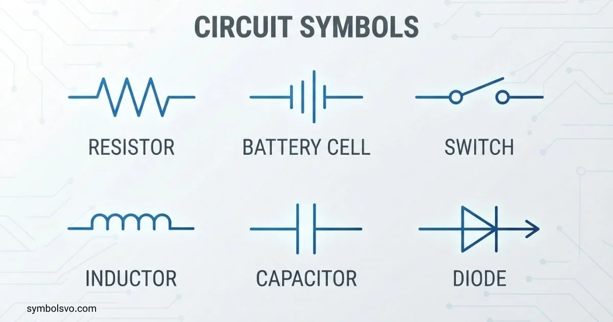
Basic circuit symbols represent the components and connections found in simple circuits. Students usually meet these symbols first when learning electricity and circuit diagrams.
Here are some of the most useful basic symbols:
| Symbol | Common name | Main purpose | ||||
| ───── | Wire | Connects components | ||||
| ⏚ | Earth/ground | Shows an earth or reference connection, depending on the diagram | ||||
| ─o o─ | Open switch | Interrupts the circuit | ||||
| ─o─o─ | Closed switch | Completes the circuit | ||||
| ──///── | Resistor | Limits current | ||||
| ── | ── | Capacitor | Stores electrical charge | |||
| ──( )── | Inductor/coil | Stores energy in a magnetic field | ||||
| ── | > | ── | Diode | Allows current primarily in one direction | ||
| ──(X)── | Lamp | Converts electrical energy into light | ||||
| ──(M)── | Motor | Converts electrical energy into mechanical motion | ||||
| ── | ── | Cell | Provides electrical energy | |||
| ── | ─ | ── | Battery | Represents multiple cells |
The exact appearance of some symbols can vary between drawing conventions and standards. For example, resistor symbols are commonly shown as a zigzag in many North American diagrams, while a rectangular resistor symbol is common in IEC-style diagrams.
Circuit Symbols And Names
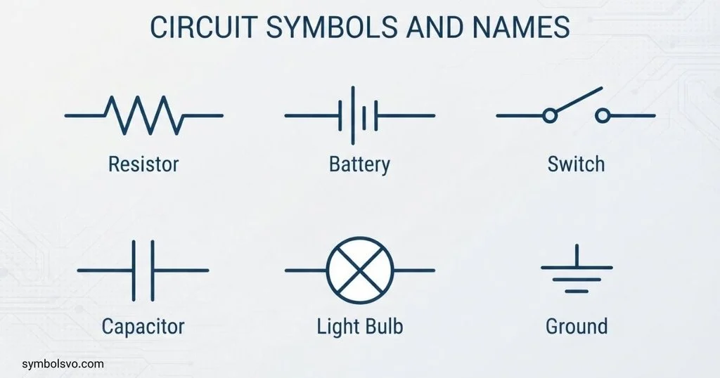
Knowing the name of a symbol is the first step toward reading a schematic. A symbol provides a compact visual representation of a component or connection.
Some common circuit symbols and names include:
- Resistor — ──///──
- Capacitor — ──| |──
- Polarized capacitor — ──| |── with polarity marking
- Inductor — ──∿∿∿──
- Diode — ──|>|──
- LED — diode symbol with arrows pointing outward
- Switch — a break in the conductor with a movable contact
- Lamp — a circle containing a cross
- Motor — commonly shown as a circle containing M
- Cell — two parallel plates of unequal length
- Battery — multiple cell pairs
- Transformer — two coils separated by core lines
- Fuse — a protective component symbol placed in series
- Ground — a reference or grounding symbol
- Antenna — a symbol representing an electrical connection to an antenna
A symbol’s orientation may change when a schematic is drawn. A resistor, for example, can be placed horizontally or vertically without changing its basic function.
Circuit Symbols And Meanings
The meaning of a circuit symbol comes from the component or connection it represents.
For example, a resistor tells you that the circuit contains a component designed to provide electrical resistance. A capacitor indicates a component that stores electrical energy in an electric field. A diode indicates a semiconductor device with directional current behavior.
Here are several common meanings:
| Symbol type | Meaning |
| Resistor | Resistance in the circuit |
| Capacitor | Electrical charge storage |
| Inductor | Magnetic energy storage |
| Diode | Rectifying or directional semiconductor behavior |
| LED | Light-emitting diode |
| Switch | Circuit control |
| Cell | Electrical source |
| Battery | Group of cells or a battery source |
| Ground | Electrical reference or grounding connection |
| Fuse | Overcurrent protection |
| Motor | Electrical-to-mechanical energy conversion |
| Transformer | Magnetic coupling between circuits |
The symbol alone may not tell you every specification. Values, labels, polarity marks, reference designators, and other annotations provide additional information.
Circuit Symbols And Functions
Circuit symbols help identify what each part does within a circuit.
A resistor controls resistance and is often used to limit current or create voltage relationships. A capacitor stores and releases electrical energy. An inductor stores energy in a magnetic field and opposes changes in current.
A switch controls whether a conductive path is open or closed. A diode is used for functions such as rectification and protection. An LED produces light when operated correctly.
Power sources such as cells and batteries provide electrical energy. Motors convert electrical energy into motion, while lamps convert electrical energy into light.
This makes circuit diagrams much easier to understand. Instead of explaining every component in words, the schematic communicates the basic structure visually.
Common Circuit Symbols
The following symbols appear frequently in basic electrical and electronic diagrams:
| Component | Symbol style | Function | ||
| Wire | ───── | Provides a conductive connection | ||
| Switch | ─o/ o─ | Opens or closes a path | ||
| Resistor | ──///── or rectangle | Provides resistance | ||
| Capacitor | ── | ── | Stores charge | |
| Diode | ── | > | ── | Controls current direction |
| LED | Diode with outward arrows | Produces light | ||
| Inductor | Coil | Stores magnetic energy | ||
| Fuse | Fuse element | Provides overcurrent protection | ||
| Lamp | Circle with cross | Produces light | ||
| Motor | Circle with M | Produces mechanical motion | ||
| Cell | Unequal parallel plates | Supplies electrical energy | ||
| Battery | Several cell symbols | Supplies electrical energy | ||
| Ground | Ground symbol | Provides a reference or grounding point |
A circuit may contain many other symbols, but these are useful starting points for beginners.
All Circuit Symbols
There is no short list containing every circuit symbol used in every field. Modern electrical and electrotechnical diagrams can contain a very large number of standardized graphical symbols.
IEC 60617 is the international IEC database for graphical symbols used in diagrams. It covers areas including conductors and connections, passive components, semiconductor devices, electrical energy systems, switchgear, measuring equipment, and telecommunications.
Some broad categories include:
- Conductors and connections
- Switches and control devices
- Resistors
- Capacitors
- Inductors
- Transformers
- Diodes
- Transistors
- Integrated circuits
- Power sources
- Measuring instruments
- Motors and generators
- Lamps and indicators
- Protective devices
- Communication components
- Logic functions
- Electrical installation symbols
Because different disciplines use different symbol sets, a complete professional symbol library is much larger than a basic school chart.
Electrical Circuit Symbols
Electrical circuit symbols are used to represent components and connections in electrical systems. They appear in wiring diagrams, power-system diagrams, control circuits, installation drawings, and other technical documents.
Common electrical symbols include:
- Switch: controls a circuit path
- Fuse: protects against excessive current
- Circuit breaker: provides switching and protection
- Lamp: represents a lighting load
- Motor: represents an electrical machine
- Generator: represents electrical power generation
- Transformer: represents electrical energy transfer through magnetic coupling
- Earth: indicates an earth connection where applicable
- Cell or battery: represents a source of electrical energy
- Relay: represents an electrically controlled switching device
Electrical symbols are especially useful because they allow a large installation to be represented without drawing the physical appearance of every device.
Electronic Circuit Symbols
Electronic circuit symbols are used for components found in electronic circuits, including semiconductor devices and passive components.
Some important examples are:
| Component | Symbol concept | Typical use |
| Resistor | Zigzag or rectangle | Current and voltage control |
| Capacitor | Two plates | Filtering and energy storage |
| Inductor | Coil | Filtering and magnetic energy storage |
| Diode | Triangle-like direction is not used; standard diode symbol has a triangle-free diode form | Rectification and protection |
| LED | Diode with light arrows | Indication and lighting |
| Transistor | Semiconductor transistor symbol | Switching and amplification |
| Photodiode | Diode with incoming arrows | Light detection |
| Zener diode | Diode with modified cathode marking | Voltage regulation and protection |
| IC | Block-style representation | Complex electronic functions |
| Crystal | Crystal resonator symbol | Frequency control |
Electronic schematics often use reference designators such as R for resistors, C for capacitors, and L for inductors. The exact conventions can depend on the schematic standard and application.
Schematic Circuit Symbols
Schematic circuit symbols are the visual language used in circuit diagrams. They allow engineers, technicians, students, and designers to describe electrical relationships without drawing each component as it physically appears.
A schematic usually shows:
- Components
- Electrical connections
- Component values
- Reference designators
- Input and output points
- Power connections
- Ground or reference points
- Relevant labels and notes
For example, a resistor may be labeled R1, while a capacitor may be labeled C1. The labels distinguish individual components when several of the same type appear in one circuit.
A schematic is different from a physical layout. A schematic focuses on electrical relationships, while a layout shows where components and connections are physically positioned.
Circuit Symbols Physics
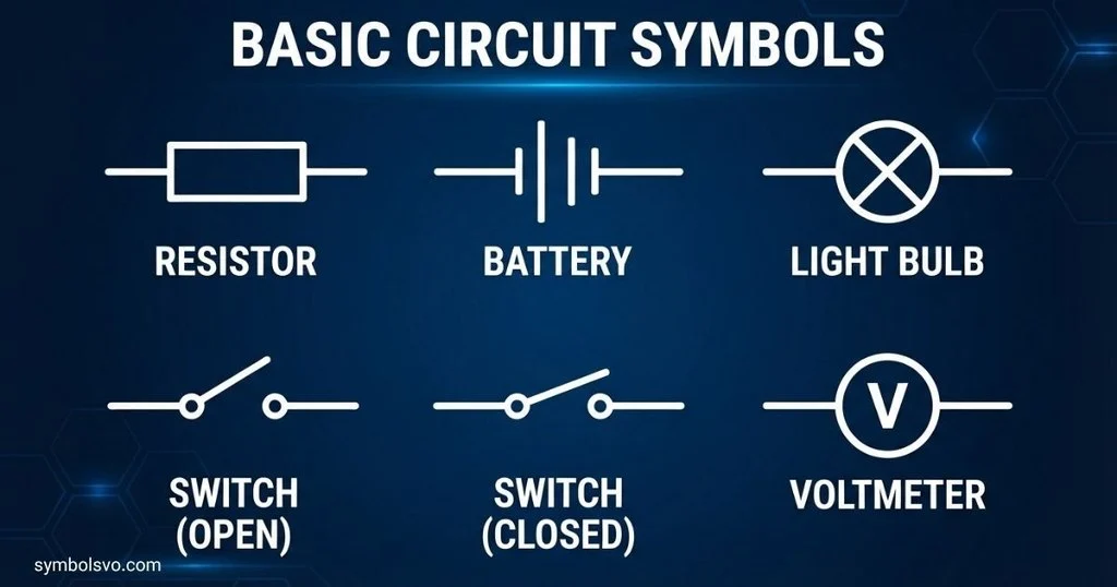
In physics, circuit symbols are used to simplify electrical circuits into clear diagrams. They help students study current, voltage, resistance, electrical energy, and circuit behavior.
A simple circuit might contain:
Cell → Switch → Lamp → Wire → Cell
The cell supplies energy. The switch controls the circuit. The lamp acts as a load, and the wires provide the conducting path.
Some symbols commonly encountered in school physics include:
- Cell
- Battery
- Wire
- Switch
- Lamp
- Resistor
- Variable resistor
- Ammeter
- Voltmeter
- Diode
- Motor
- Fuse
Physics diagrams are often simplified so students can focus on the electrical relationships rather than the physical appearance of components.
Logic Circuit Symbols
Logic circuit symbols represent digital logic functions. They are used to show how binary inputs are processed to produce outputs.
Common logic gates include:
| Gate | Basic function |
| AND | Output is 1 when all required inputs are 1 |
| OR | Output is 1 when at least one input is 1 |
| NOT | Produces the inverse of the input |
| NAND | Inverted AND function |
| NOR | Inverted OR function |
| XOR | Output is 1 when inputs differ |
| XNOR | Output is 1 when inputs are equal |
Logic gates can have different numbers of inputs, depending on the circuit.
A small circle, called a bubble in many logic diagrams, can indicate inversion at an input or output. For example, a NAND gate can be represented as an AND function with an inverted output.
Logic symbols are used in digital electronics, processors, control systems, computers, and many other technologies.
Hydraulic Circuit Symbols
Hydraulic circuit symbols represent components used in systems that transmit power through pressurized fluids. These symbols are different from ordinary electrical circuit symbols.
Common hydraulic diagram elements include:
- Hydraulic pump
- Hydraulic motor
- Reservoir
- Filter
- Pressure gauge
- Check valve
- Relief valve
- Directional control valve
- Hydraulic cylinder
- Flow control valve
- Pressure control components
- Hydraulic lines
Hydraulic symbols are usually designed around the function of the component rather than its physical appearance.
For example, a hydraulic cylinder represents linear mechanical movement produced by fluid pressure. A directional control valve determines the path through which hydraulic fluid flows.
Hydraulic diagrams are commonly used to understand fluid paths, pressure control, actuator movement, and system operation.
Pneumatic Circuit Symbols
Pneumatic circuit symbols represent components in systems powered by compressed air or gas.
Common pneumatic components include:
- Compressor
- Air reservoir
- Filter
- Regulator
- Lubricator
- Pressure gauge
- Directional control valve
- Flow control valve
- Check valve
- Pneumatic cylinder
- Pneumatic motor
- Exhaust connection
A pneumatic cylinder symbol represents an actuator that can convert compressed air energy into mechanical movement.
Pneumatic diagrams are useful for showing how air moves through valves and actuators. They also help technicians understand the sequence and control of automated machinery.
Hydraulic and pneumatic symbols should not be treated as interchangeable. Although both systems use fluid power, their components and diagram conventions can differ.
Circuit Symbols Resistor
The resistor is one of the most common components in electrical and electronic circuits.
Two common graphical forms are:
US-style resistor: ──/\/\/──
IEC-style resistor: ──[ ]──
The rectangular form is commonly associated with IEC-style diagrams, while the zigzag form is widely used in North American schematics. Both can represent a fixed resistor, depending on the drawing convention.
A resistor provides electrical resistance. It can be used to limit current, establish voltage relationships, bias electronic components, and dissipate electrical energy as heat.
A resistor may be labeled R1, R2, R3, and so on. Its value is usually given in ohms, represented by Ω.
Variable resistors have additional graphical features to show that their resistance can be adjusted.
When reading a resistor in a schematic, check the symbol, reference designator, value, and any associated power or tolerance information.
Circuit Symbols Cell
A cell is a source of electrical energy. Its common circuit symbol consists of two parallel lines of unequal length.
A simplified representation is:
──| |──
The longer line conventionally represents the positive terminal, while the shorter line represents the negative terminal in the common schematic representation.
A battery is commonly represented by multiple cell elements:
──| |─| |──
A cell can supply energy to a circuit, allowing current to flow when the circuit provides a complete conducting path.
A cell symbol is often used in school physics diagrams and basic electrical circuits. Real cells come in many physical forms, but the schematic symbol focuses on their electrical function rather than their physical shape.
Circuit Symbols Chart
A circuit symbols chart is useful when you need to identify an unfamiliar component quickly.
| Symbol | Name | Meaning or function | ||||
| ───── | Wire | Electrical connection | ||||
| ─o o─ | Open switch | Circuit path open | ||||
| ─o─o─ | Closed switch | Circuit path closed | ||||
| ──///── | Resistor | Resistance | ||||
| ──[ ]── | Resistor | IEC-style resistor representation | ||||
| ── | ── | Capacitor | Charge storage | |||
| ── | > | ── | Diode | Semiconductor with directional behavior | ||
| ──∿∿∿── | Inductor | Magnetic energy storage | ||||
| ⎓ | DC indication | Direct-current context | ||||
| ∿ | AC indication | Alternating-current context | ||||
| ⏚ | Earth/ground | Grounding/reference context | ||||
| ⊗ | Lamp-style symbol | Light-producing load in many diagrams | ||||
| Ⓜ | Motor-style label | Motor representation in simplified diagrams | ||||
| ── | ── | Cell | Electrical source | |||
| ── | ─ | ── | Battery | Multiple cells |
The exact drawing of some symbols depends on the standard, field, and diagram style. For professional work, use the applicable standard rather than relying on a generic online chart.
Electrical Circuit Symbols Chart
An electrical circuit symbols chart is most useful when grouped by function.
| Category | Common symbols/components | Typical purpose |
| Sources | Cell, battery, generator | Supply electrical energy |
| Connections | Wire, terminal, junction | Connect circuit elements |
| Control | Switch, push button, relay | Control circuit operation |
| Protection | Fuse, circuit breaker | Protect circuits |
| Loads | Lamp, motor, heater | Use electrical energy |
| Passive | Resistor, capacitor, inductor | Control or store electrical energy |
| Conversion | Transformer, rectifier | Change electrical characteristics |
| Measurement | Ammeter, voltmeter | Measure electrical quantities |
| Grounding | Earth, chassis/reference symbols | Provide a reference or grounding connection |
This type of chart is useful for introductory electrical diagrams because it connects the visual symbol with the job performed by the component.
Remember that a symbol’s exact meaning can depend on the surrounding diagram. A professional drawing should be interpreted using its legend, applicable standard, labels, and context.
Electronic Circuit Symbols Chart
An electronic circuit symbols chart focuses more heavily on components used in electronic circuits.
| Component | Symbol description | Common function |
| Resistor | Zigzag or rectangle | Resistance and current control |
| Capacitor | Two plates | Filtering and charge storage |
| Inductor | Coil | Filtering and magnetic energy storage |
| Diode | Diode symbol | Rectification and protection |
| LED | Diode with light arrows | Light indication |
| Zener diode | Modified diode symbol | Voltage regulation/protection |
| Photodiode | Diode with arrows toward it | Light sensing |
| Transistor | Semiconductor symbol | Switching/amplification |
| Operational amplifier | Triangle-shaped block | Analog signal processing |
| Logic gate | Gate-specific outline | Digital logic |
| Transformer | Coupled coils | Magnetic energy transfer |
| Crystal | Resonator symbol | Frequency control |
Electronic symbols are designed to make circuit relationships readable. The component’s value and identifying label are normally placed near the symbol.
For example, a schematic might contain R1 = 1 kΩ, C1 = 10 µF, or D1 for a diode. These labels provide information that the graphical symbol alone cannot provide.
Why Circuit Symbols Matter
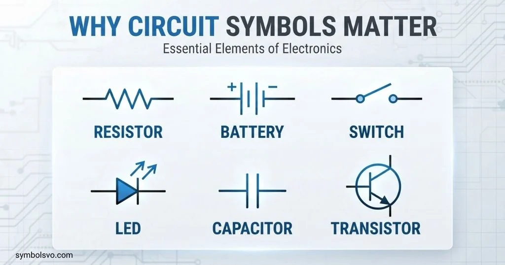
Circuit symbols are a compact technical language. They allow people to communicate circuit designs without needing to draw realistic pictures of every component.
The IEC maintains IEC 60617, a database of standardized graphical symbols for diagrams. Its current database contains more than 1,500 graphical symbols and covers categories ranging from passive components and conductors to semiconductor devices, switchgear, measuring equipment, and telecommunications.
For that reason, a generic internet chart should be treated as a learning aid rather than a replacement for the applicable technical standard. Symbol conventions can differ between disciplines and regions, especially for items such as resistors.
Frequently Asked Questions
What Are Circuit Symbols Used For?
Circuit symbols are used to represent electrical or electronic components and connections in diagrams. They make circuits easier to design, read, explain, document, and troubleshoot.
What Is The Most Common Circuit Symbol?
There is no single most common symbol for every type of circuit. Wires, resistors, switches, power sources, capacitors, and diodes are among the symbols frequently encountered in basic electrical and electronic diagrams.
What Is The Symbol For A Resistor?
A resistor is commonly shown as a zigzag line in many North American schematics and as a rectangular box in IEC-style diagrams. Both conventions can represent a fixed resistor.
What Is The Symbol For A Cell?
A cell is commonly represented by two parallel lines of unequal length. The longer line represents the positive terminal and the shorter line represents the negative terminal in the usual schematic convention.
Are Electrical And Electronic Circuit Symbols The Same?
There is significant overlap, but the symbol sets are not identical in practical use. Electrical diagrams may emphasize power, wiring, switching, protection, and machines, while electronic schematics commonly include semiconductor and signal-processing components.
Conclusion
Circuit symbols provide a simple way to represent complex electrical, electronic, hydraulic, and pneumatic systems. Learning the basic symbols for wires, switches, resistors, capacitors, diodes, cells, batteries, and other components makes circuit diagrams much easier to read.
The most useful approach is to learn symbols together with their names and functions. A chart can help you recognize a symbol quickly, while real schematics show how components work together in a complete system.
For accurate professional work, always consider the standard and context used by the diagram. Once you understand the basic visual language, you can move from simple physics circuits to electronic schematics, logic diagrams, and more specialized systems with much greater confidence.

I’m Nathan Holloway, a passionate researcher and writer with a deep interest in symbols, signs, and their hidden meanings. I enjoy exploring how symbols have influenced different civilizations, religions, and modern communication. Through my work, I aim to make complex historical and cultural concepts easy to understand for readers of all backgrounds. Every article I write is carefully researched to provide reliable and engaging information.
Books:
- Beyond the Symbol
- The Secret Meanings of Everyday Signs
Author 2: Grace Whitmore
Description:
My name is Grace Whitmore, and I love discovering the stories behind the world’s most fascinating symbols. I spend my time researching ancient civilizations, mythology, spiritual traditions, and modern iconography to uncover the meanings people often overlook. I believe that every symbol has a history worth telling, and I enjoy sharing that knowledge in a simple and reader-friendly way.
Books:
- Echoes of Ancient Symbols
- The Symbolic World
 Mason Ellington
 Grace Whitmore
 Daniel Brooks