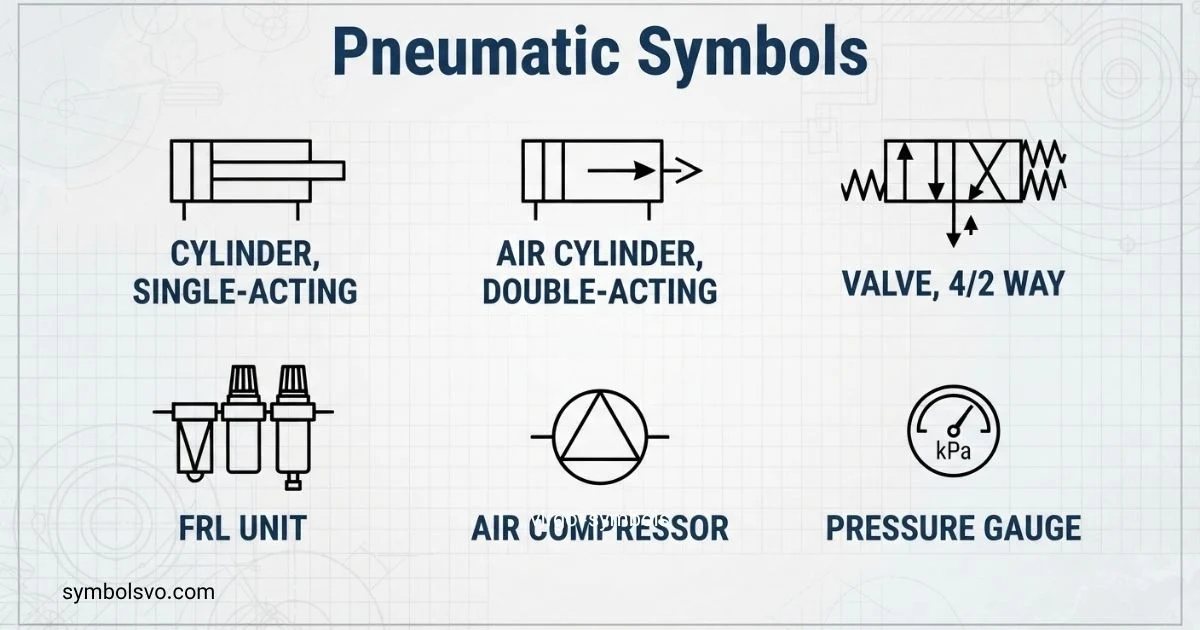
I used to think pneumatic diagrams looked complicated, but I soon learned that the symbols tell a clear story. If you are new to pneumatic systems, understanding these symbols can make diagrams much easier to follow.
You do not need to be an expert to read pneumatic symbols. I’ll help you understand what the most common symbols mean, how they work, and where you may see them in real pneumatic circuits.
Once you know the basic shapes, lines, arrows, and markings, you can read pneumatic diagrams with much more confidence. You can use this guide as a simple reference whenever you need to identify or understand a pneumatic symbol.
Basic Pneumatic Symbols
Basic pneumatic symbols provide a visual language for representing the main parts of an air-powered system. They show what a component does rather than trying to reproduce its physical appearance.
Common groups include:
| Component | What the symbol represents | Typical function |
| Compressor | Pneumatic energy source | Produces compressed air |
| Reservoir | Stored compressed air | Holds air for the system |
| Filter | Air-treatment component | Removes contaminants |
| Regulator | Pressure-control component | Maintains a selected pressure |
| Lubricator | Air-treatment component | Adds lubricant where required |
| Valve | Control component | Starts, stops, or directs airflow |
| Cylinder | Linear actuator | Produces linear motion |
| Motor | Rotary actuator | Produces rotary motion |
| Flow-control valve | Flow-control component | Adjusts airflow rate |
| Silencer | Exhaust component | Reduces exhaust noise |
The exact graphical form depends on the applicable symbol standard and the level of detail required. ISO 1219-1 defines rules for fluid-power graphical symbols used on components and circuit diagrams.
A useful way to read a pneumatic diagram is to identify three things first:
- Energy source — Where does the compressed air come from?
- Control elements — Which valves control the air?
- Actuators — Which cylinders or motors turn air energy into movement?
Once these three groups are clear, the rest of the diagram becomes much easier to follow.
Pneumatic Symbols And Meanings
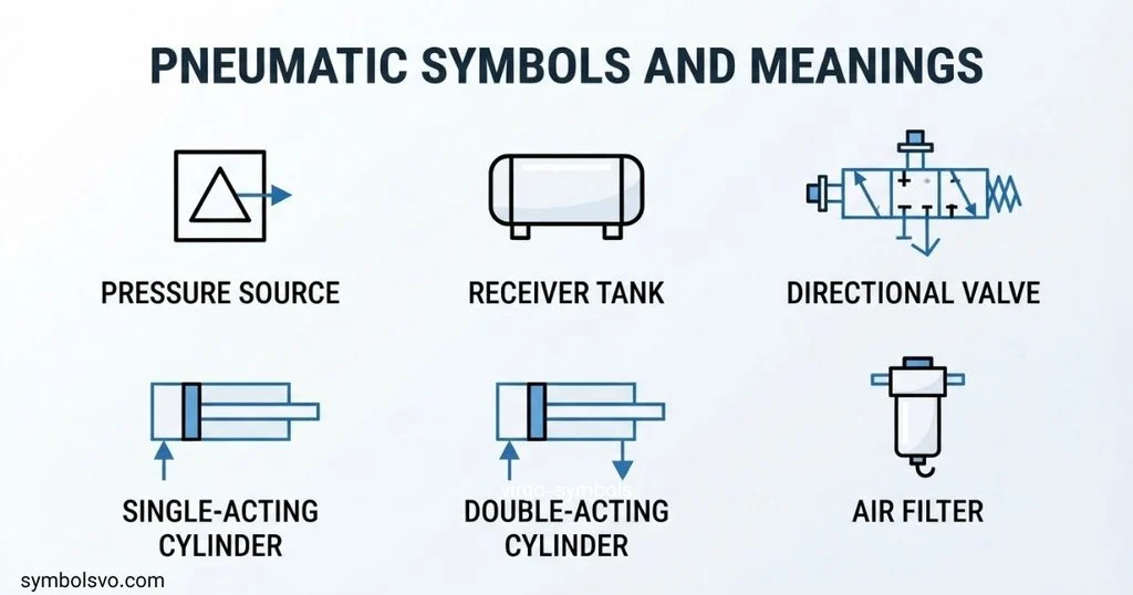
The meaning of a pneumatic symbol comes from its graphical elements and its position within the circuit. A symbol should be interpreted according to the relevant standard rather than by guessing what the physical component looks like.
For example, directional control valve symbols communicate information about ports, positions, and flow paths. A cylinder symbol identifies an actuator, while additional marks can indicate features such as cushioning or a particular operating arrangement.
Some common meanings are:
- Cylinder — converts compressed-air energy into linear movement.
- Pneumatic motor — converts compressed-air energy into rotary movement.
- Directional valve — controls the direction of air.
- Pressure regulator — controls downstream pressure.
- Filter — removes particles and other contaminants from compressed air.
- Flow-control device — controls the rate of air movement.
- Silencer — fitted at an exhaust point to reduce noise.
- Connection point — identifies where components or lines are connected.
Symbols can also contain arrows, lines, boxes, circles, or other graphical elements. Their meaning depends on how they are combined, so a single mark should not always be interpreted independently.
Pneumatic Symbols With Explanation
A pneumatic diagram can look complicated at first because several symbols may be connected into one system. The easiest approach is to read each symbol as a functional description.
Energy source
The beginning of a pneumatic system commonly includes the source of compressed air. A compressor supplies the air, while a reservoir may store it before distribution.
Air preparation
Filters, regulators, and lubricators may appear together as an air-preparation group. Their purpose is to prepare compressed air for downstream equipment.
Directional control
Directional valves determine where compressed air is sent. Their graphical representation provides information about ports and possible flow paths.
Actuation
Cylinders and pneumatic motors are the components that perform useful mechanical work. A cylinder generally produces linear movement, while a pneumatic motor produces rotary movement.
Exhaust and flow control
Exhaust symbols and flow-control elements help describe how air leaves or moves through the circuit. These details are important when analyzing movement speed and operating behavior.
A key point is that pneumatic symbols are functional representations. They do not necessarily resemble the physical component installed on a machine.
Pneumatic Symbols Chart
A pneumatic symbols chart is most useful when it groups symbols by function rather than presenting an unorganized collection.
| Symbol category | Examples | What to look for |
| Energy supply | Compressor, reservoir | Source and storage of compressed air |
| Air preparation | Filter, regulator, lubricator | Conditioning and pressure control |
| Directional control | 2/2, 3/2, 4/2, 5/2 valves | Number of ports and positions |
| Actuators | Single-acting cylinder, double-acting cylinder | Type and direction of movement |
| Flow control | Throttle and flow-control devices | Airflow adjustment |
| Pressure control | Regulator, pressure-related devices | Pressure management |
| Exhaust | Silencer | Air discharge |
| Connections | Ports and lines | How components are connected |
For technical work, a chart should always be checked against the symbol standard being used. ISO 1219-1 establishes the graphical-symbol framework, while ISO 1219-2 addresses rules for drawing hydraulic and pneumatic circuit diagrams.
Pneumatic Symbols and Functions
Pneumatic symbols describe the function of a component inside a circuit.
A few important relationships are:
- Compressor → supplies compressed air
- Filter → conditions incoming air
- Regulator → controls pressure
- Directional valve → controls air direction
- Flow-control valve → controls flow rate
- Cylinder → produces linear motion
- Pneumatic motor → produces rotary motion
- Silencer → manages exhaust discharge
The same component may have different operating details depending on the complete circuit. For example, a directional valve symbol alone does not tell the whole story of a machine. Its connections, actuation method, valve positions, and associated components must also be considered.
This is why pneumatic diagrams should be read as connected systems rather than as isolated symbols.
Pneumatic Valve Symbols
Pneumatic valve symbols are among the most important symbols to understand because valves control how compressed air moves through a circuit.
Directional-control valve symbols are commonly described by their number of ports and positions. For example:
- 2/2 valve — two ports and two switching positions.
- 3/2 valve — three ports and two switching positions.
- 4/2 valve — four ports and two switching positions.
- 5/2 valve — five ports and two switching positions.
- 5/3 valve — five ports and three switching positions.
The boxes used in a directional valve symbol represent the valve’s positions. Lines and arrows inside those positions show the relevant flow paths. External marks can show how the valve is actuated or returned.
Common actuation types include:
- Manual push button
- Lever
- Pedal
- Roller
- Pneumatic actuation
- Solenoid actuation
- Spring return
Festo’s pneumatic training material shows examples of directional-control valves, including 2/2 and 3/2 valves, and identifies representations according to ISO 1219-1.
Pneumatic Symbols Regulator
A pneumatic regulator symbol represents a pressure-control function in a compressed-air circuit. Regulators are used to maintain a desired downstream pressure rather than simply allowing supply pressure to pass through unchanged.
When reading a regulator symbol, look at:
- The main flow direction.
- The pressure-control representation.
- Any spring or adjustment indication.
- The connection points.
- Whether a gauge or other pressure-monitoring component is shown separately.
A regulator is often associated with an air-preparation assembly. In practical diagrams, it may appear near a filter and other conditioning components.
The symbol should not be confused with a flow-control symbol. A pressure regulator controls pressure, while a flow-control device primarily controls airflow rate.
All Pneumatic Symbols
There is no single short list that can represent every pneumatic symbol used in every drawing. Pneumatic systems can combine symbols for energy sources, valves, actuators, pressure devices, flow devices, air preparation, exhaust, connections, and specialized components.
A practical classification is:
Air supply symbols
These can represent:
- Compressor
- Pneumatic energy source
- Reservoir
- Air connection
- Exhaust or discharge
Valve symbols
These include symbols for:
- Directional-control valves
- Check valves
- Flow-control valves
- Pressure-control valves
- Shut-off functions
- Special valve arrangements
Actuator symbols
Typical actuator categories include:
- Single-acting cylinders
- Double-acting cylinders
- Pneumatic motors
- Rotary or semi-rotary actuators
Air-treatment symbols
These cover components such as:
- Filters
- Regulators
- Lubricators
- Filter-regulator combinations
Control and connection symbols
These communicate:
- Port connections
- Lines
- Junctions
- Actuation methods
- Exhaust arrangements
- Control signals
For engineering work, “all pneumatic symbols” should therefore be understood as a symbol system rather than a fixed Unicode character collection.
ISO Pneumatic Symbols
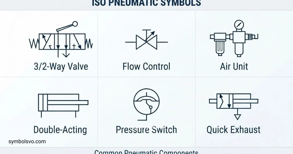
ISO pneumatic symbols are standardized graphical representations used for fluid-power systems. The key reference is ISO 1219-1, which specifies basic elements and rules for devising fluid-power symbols used on components and circuit diagrams.
ISO symbols are designed to communicate function consistently. They are therefore different from decorative text symbols such as ★, ✓, or arrows that can be copied directly into ordinary text.
The ISO approach is especially useful when engineers from different companies or countries need to interpret the same technical drawing.
ISO 1219 is closely associated with hydraulic and pneumatic applications, so the same overall symbol framework can appear in both areas.
ISO 1219 Pneumatic Symbols
ISO 1219 pneumatic symbols are part of the broader ISO 1219 fluid-power symbol system. ISO 1219-1:2012 is titled Fluid power systems and components — Graphical symbols and circuit diagrams — Part 1: Graphical symbols for conventional use and data-processing applications. ISO states that the 2012 edition is the current published version and has an amendment from 2016.
The standard provides rules for constructing fluid-power symbols rather than giving every pneumatic component a simple Unicode character.
For circuit diagrams, ISO 1219-2 is also relevant. It establishes the main rules for drawing hydraulic and pneumatic circuit diagrams using graphical symbols based on ISO 1219-1.
This distinction matters:
- ISO 1219-1 — graphical symbols.
- ISO 1219-2 — circuit diagrams.
- ISO 1219-3 — symbol modules and connected symbols in circuit diagrams.
ISO 1219-3 supplements the earlier parts by defining rules for generating and combining symbols for connectable components.
ISO 1219 Pneumatic Symbols Standard
The ISO 1219 standard is useful because it creates a common graphical language for fluid-power documentation.
When someone searches for an “ISO 1219 pneumatic symbols standard,” they are usually looking for standardized representations that can be used when designing or interpreting pneumatic circuit diagrams.
The current ISO information identifies ISO 1219-1:2012 as the published edition for graphical symbols, with Amendment 1:2016. ISO 1219-2:2012 covers circuit diagrams, and ISO 1219-3:2016 covers symbol modules and connected symbols.
Older ISO 1219-1 editions should not automatically be treated as the current reference. For example, ISO 1219-1:2006 is listed as withdrawn and replaced by the 2012 edition.
For formal engineering documentation, the applicable edition and any required company or regional conventions should always be verified before a drawing is released.
Hydraulic Pneumatic Symbols
Hydraulic and pneumatic diagrams use many related graphical principles because both belong to fluid-power engineering. ISO 1219 provides a common framework for fluid-power graphical symbols and circuit diagrams.
The major difference is the working medium and the components used to control it:
| Pneumatic system | Hydraulic system |
| Uses compressed gas, commonly air | Uses liquid fluid |
| Often uses compressors | Often uses hydraulic pumps |
| Uses pneumatic cylinders and motors | Uses hydraulic cylinders and motors |
| Includes air preparation | Includes hydraulic filtration and fluid management |
| Exhausts air | Returns hydraulic fluid to the circuit or reservoir |
Some symbol concepts are similar, but the complete circuit and component representation must be interpreted according to the relevant fluid-power application.
Do not assume that a hydraulic drawing and a pneumatic drawing are interchangeable simply because some graphical conventions look similar.
Festo Pneumatic Symbols
Festo publishes pneumatic training and technical material that uses standardized representations for pneumatic components. Its educational material includes examples of pneumatic energy sources, valves, cylinders, pneumatic motors, actuation methods, and ISO 1219-1 representations.
Festo material can therefore be useful when learning how pneumatic diagrams are structured, especially when studying valve functions and control circuits.
However, a manufacturer symbol library should not automatically be treated as a replacement for the applicable international standard. A manufacturer’s documentation may include additional identifiers, product-specific information, or presentation conventions alongside standardized graphical symbols.
When studying Festo pneumatic symbols, focus on the relationship between:
- The component name.
- The standardized graphical representation.
- The component’s function.
- The way it connects to the rest of the circuit.
That approach makes the knowledge transferable to diagrams from other manufacturers.
Visio Pneumatic Symbols
Microsoft Visio can be used to create technical diagrams, but the exact availability of pneumatic shapes depends on the Visio version, installed templates, and available shape libraries.
When creating a pneumatic diagram in Visio, the most important consideration is not simply finding a shape that looks correct. The shape should represent the intended technical function and follow the standard required for the project.
For a standards-based drawing, check:
- Component identity.
- Number of valve ports.
- Number of valve positions.
- Flow-path representation.
- Actuation method.
- Connection points.
- Direction of flow where applicable.
- Required drafting standard.
If a built-in shape does not match the required standard, a custom or imported technical shape may be necessary. The finished drawing should still be checked against the relevant documentation standard rather than relying only on the appearance of a Visio shape.
Autocad Pneumatic Symbols
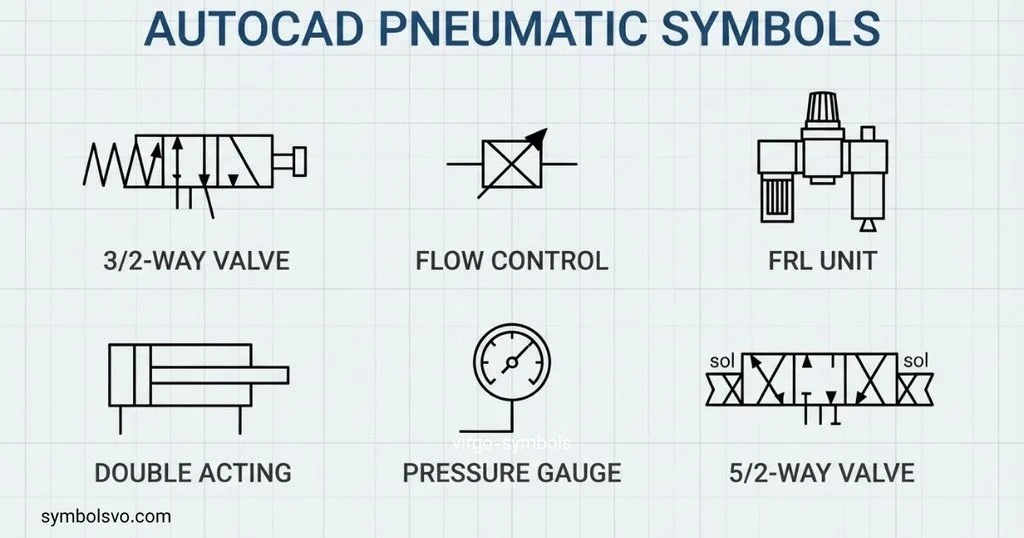
AutoCAD Electrical includes dedicated pneumatic component functionality and a pneumatic symbol library. Autodesk documentation states that pneumatic components can be inserted from an on-screen icon menu, and its pneumatic library includes a pneu_iso125 library.
The software can also distinguish pneumatic and hydraulic component libraries. Autodesk documentation identifies pneumatic libraries such as pneu_iso125 and pneu_mm, alongside separate hydraulic libraries.
This makes AutoCAD useful for technical pneumatic schematics where reusable symbol blocks are needed.
When working with AutoCAD pneumatic symbols, check the project settings before inserting components. A symbol library may be based on a particular standard, size convention, or company drafting requirement.
AutoCAD Electrical also allows pneumatic symbols to be customized and added to an icon menu, which can be useful for company-specific drafting workflows.
Pneumatic Symbols And Functions
The easiest way to learn pneumatic symbols is to connect every graphical representation with a physical function.
| Function | Typical component | What to understand |
| Generate air | Compressor | Creates compressed air |
| Store air | Reservoir | Stores compressed air |
| Clean air | Filter | Removes unwanted particles |
| Control pressure | Regulator | Maintains selected pressure |
| Direct air | Directional valve | Selects flow paths |
| Prevent reverse flow | Check valve | Allows flow primarily in one direction |
| Control speed | Flow-control device | Adjusts airflow |
| Create linear motion | Cylinder | Converts air energy into movement |
| Create rotary motion | Pneumatic motor | Produces rotary movement |
| Reduce exhaust noise | Silencer | Attenuates exhaust sound |
The function is often more useful than memorizing the shape alone. Once you understand what a valve or actuator does, its symbol becomes much easier to recognize in a complete circuit.
A good learning method is to study one category at a time: air supply, air treatment, valves, flow control, actuators, and then complete circuits.
Pneumatic Symbols Chart
A second look at a pneumatic symbols chart is useful when you need a quick reference while reading a drawing.
| Category | Common examples | Main question to ask |
| Supply | Compressor, reservoir | Where does the air originate? |
| Preparation | Filter, regulator | How is the air conditioned? |
| Directional control | 3/2, 5/2 valves | Where can the air go? |
| Pressure control | Regulator | What pressure is maintained? |
| Flow control | Flow-control valve | How quickly does air move? |
| Actuation | Cylinder, motor | What movement is produced? |
| Exhaust | Silencer | Where does air leave? |
| Connections | Lines, ports | How are components linked? |
The chart is best used as a recognition aid. For formal interpretation, consult the applicable standard and the original equipment documentation.
FAQ
What are pneumatic symbols used for?
Pneumatic symbols are used to represent compressed-air components and their functions in technical diagrams. They allow engineers and technicians to understand a circuit without drawing every physical component.
What standard is used for pneumatic symbols?
ISO 1219 is a major international reference for fluid-power graphical symbols and circuit diagrams. ISO 1219-1 covers graphical symbols, while ISO 1219-2 covers circuit-diagram rules.
Are pneumatic symbols Unicode characters?
Generally, no. Pneumatic circuit symbols are graphical engineering symbols rather than a standard collection of copy-and-paste Unicode characters. They are normally created and displayed in technical drawings or CAD software.
What is the difference between a 3/2 and 5/2 pneumatic valve?
The numbers describe the valve’s ports and positions. A 3/2 valve has three ports and two positions, while a 5/2 valve has five ports and two positions. The actual circuit function depends on the flow paths and actuation arrangement shown by the complete symbol.
Can I create pneumatic diagrams in AutoCAD?
Yes. AutoCAD Electrical provides tools and libraries for inserting pneumatic components, including dedicated pneumatic symbol libraries. Autodesk documents a pneu_iso125 library and tools for inserting and customizing pneumatic components.
Conclusion
Pneumatic symbols provide a compact way to describe compressed-air systems. Once you understand supply components, valves, regulators, flow-control devices, actuators, exhaust elements, and connections, even a complex pneumatic diagram becomes easier to read.
ISO 1219 provides an important foundation for standardized fluid-power symbols and circuit diagrams, while tools such as AutoCAD and manufacturer training resources can make those symbols easier to apply in practical design work.
The most useful approach is to learn symbols by function instead of memorizing shapes without context. Use a reference chart for quick recognition, check the applicable standard for formal drawings, and always interpret each symbol as part of the complete pneumatic circuit.

 Grace Whitmore
 Daniel Brooks