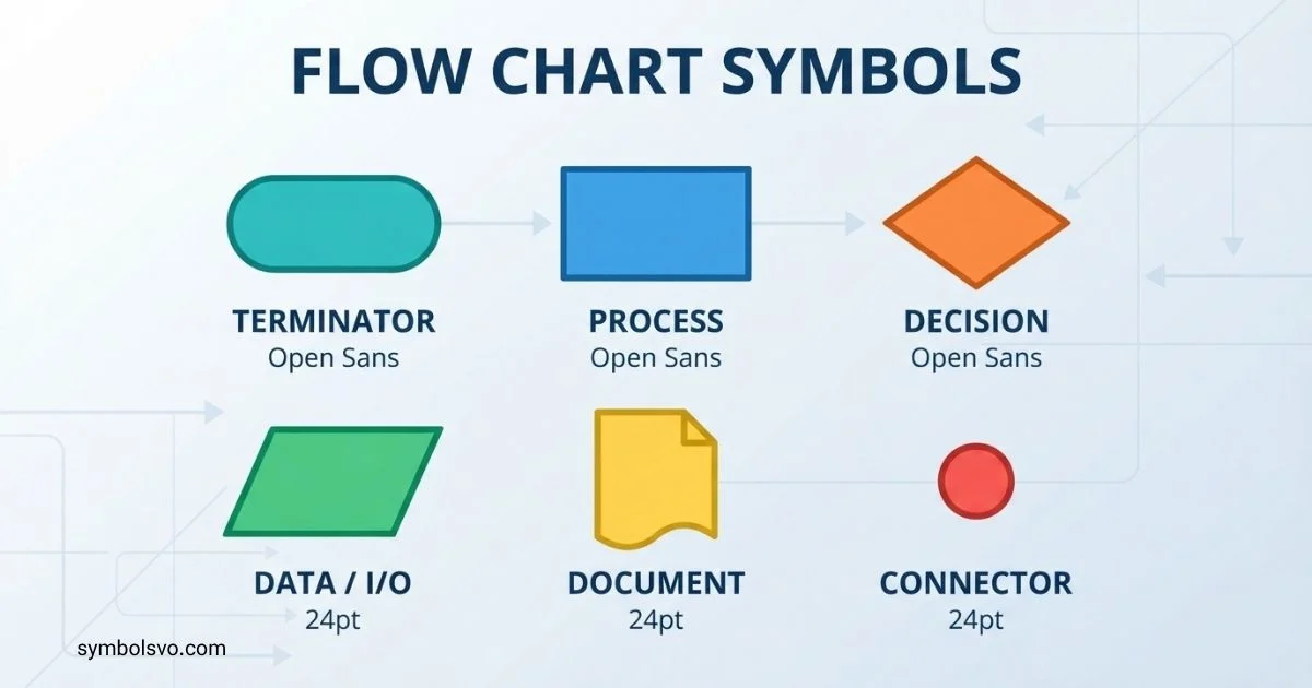
When I first started using flowcharts, I quickly realized that the symbols can feel confusing. You may know what a flowchart does, but understanding what each shape means can make your diagrams much clearer.
I want to make this simple for you. Flow chart symbols help you show processes, decisions, inputs, outputs, and directions in a way that is easy to follow.
Whether you are a beginner, student, designer, or professional, I’ll walk you through the most important symbols and explain how to use them confidently.
Basic Flowchart Symbols
The basic flowchart symbols are the shapes used most often when creating a simple process diagram. You can create many useful flowcharts with only a small group of symbols.
| Symbol | Name | Main use |
| Oval | Terminator | Shows the start or end |
| Rectangle | Process | Shows an action or task |
| Diamond | Decision | Shows a question or condition |
| Arrow | Flowline | Shows the direction of flow |
| Parallelogram | Input/Output | Shows data entering or leaving |
| Circle | Connector | Connects parts of a flowchart |
| Document shape | Document | Represents a document or report |
| Cylinder | Database | Represents stored data |
For example, a simple login flow might begin with a Start oval, use a Process rectangle for entering login details, and use a Decision diamond to ask if the credentials are correct.
These symbols work because each shape gives the reader a quick visual clue about what happens at that point.
Standard Flowchart Symbols
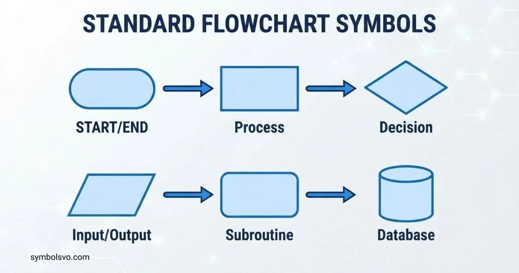
Standard flowchart symbols provide a consistent visual language for representing processes. The exact collection can vary depending on the type of diagram, but several shapes are widely recognized.
The most common standard symbols include:
- Terminator: Start or End
- Process: An operation or action
- Decision: A condition with different possible paths
- Flowline: Direction from one step to another
- Input/Output: Data entering or leaving a process
- Predefined process: A process that is defined elsewhere
- Document: A document or report
- Database: Stored information
- Connector: A connection between separated parts of a diagram
- Off-page connector: A connection to another page
Standard symbols are especially useful when several people need to understand or maintain the same diagram. Consistent shapes reduce confusion and make the flow easier to scan.
Common Flowchart Symbols
Common flowchart symbols are the shapes you are most likely to see in business, education, software, and process diagrams.
| Symbol | Meaning | Example |
| ○ / connector | Connection point | Continue flow elsewhere |
| → | Direction | Move to the next step |
| Oval | Start or end | Start process |
| Rectangle | Action | Calculate total |
| Diamond | Decision | Is payment approved? |
| Parallelogram | Input or output | Enter name |
| Cylinder | Data storage | Customer database |
| Document | Document | Generate invoice |
Not every flowchart needs every symbol. A small diagram may need only a terminator, process, decision, and flowline.
Flowchart Symbols and Their Meaning
The meaning of a flowchart symbol depends on the role it plays in the process.
Oval — Start or End: The terminator identifies where a process begins or finishes.
Rectangle — Process: A rectangle represents an action, operation, instruction, or task.
Diamond — Decision: A diamond represents a condition that can lead to different paths, such as Yes/No or True/False.
Parallelogram — Input/Output: This symbol is commonly used when information is entered into a system or displayed as output.
Arrow — Flowline: An arrow shows the direction in which the process moves.
Cylinder — Database: A cylinder commonly represents stored or persistent data.
Document — Document: A document symbol represents information produced or used as a document, such as an invoice or report.
Circle — Connector: A connector can link separated sections of a flowchart without requiring a long crossing line.
The important point is to use symbols consistently. A reader should be able to understand the role of a step by looking at its shape.
Flowchart Symbols With Examples
Examples make flowchart symbols much easier to understand. Consider a simple order process:
Oval: Start
↓
Parallelogram: Enter order details
↓
Rectangle: Check inventory
↓
Diamond: Is the product available?
From the Yes branch:
Rectangle: Process order
↓
Document: Create invoice
↓
Oval: End
From the No branch:
Rectangle: Notify customer
↓
Oval: End
This example shows how different shapes work together. The rectangle describes actions, the parallelogram handles input, the diamond controls the decision, and the document represents an output document.
What Are the 8 Basic Symbols of Flowchart
There is no single universal list that every source calls the exact “eight basic symbols.” Different standards, textbooks, and diagramming tools group flowchart symbols differently.
A practical set of eight commonly used symbols is:
- Terminator — Start or End
- Process — An action or operation
- Decision — A condition or question
- Flowline — Direction of the process
- Input/Output — Data entering or leaving
- Predefined Process — A named process defined elsewhere
- Document — A document or report
- Connector — Connects separated flowchart sections
These eight provide a strong foundation for most basic diagrams. More specialized flowcharts may add symbols for databases, manual operations, delays, displays, multiple documents, and other functions.
20 Flowchart Symbols and Their Functions
The following table provides a broader reference list of 20 useful flowchart symbols.
| # | Symbol name | Function |
| 1 | Terminator | Shows the start or end |
| 2 | Process | Shows an action or task |
| 3 | Decision | Shows a condition or question |
| 4 | Flowline | Shows the direction of flow |
| 5 | Input/Output | Represents data input or output |
| 6 | Predefined process | Represents a process defined elsewhere |
| 7 | Connector | Connects flowchart points |
| 8 | Off-page connector | Connects to another page |
| 9 | Document | Represents a document |
| 10 | Multiple documents | Represents multiple documents |
| 11 | Database | Represents stored data |
| 12 | Display | Represents information shown on a display |
| 13 | Manual input | Represents manually entered information |
| 14 | Manual operation | Represents a manually performed task |
| 15 | Preparation | Represents setup or preparation |
| 16 | Delay | Shows a waiting period |
| 17 | Merge | Shows paths coming together |
| 18 | Extract | Represents extracting part of a process or data |
| 19 | Sort | Represents arranging information into groups or order |
| 20 | Loop limit | Indicates the boundary or control of a repeated sequence |
Some specialized symbols have different names or visual conventions between diagramming systems. Always check the notation expected by the organization, course, or software you are using.
Process Flowchart Symbols
Process flowcharts show how a task or operation moves from one stage to another. They are common in business, manufacturing, administration, customer service, and quality management.
The process rectangle is the main symbol. It describes an action such as:
- Verify payment
- Pack order
- Calculate price
- Review application
- Send confirmation
The decision diamond is used when the process can take different routes.
For example:
Start → Receive order → Check stock → Stock available?
The Yes path can continue to Pack order, while the No path can go to Notify customer.
A process flowchart should make the sequence clear without requiring the reader to study long blocks of text.
Decision Flowchart Symbols
Decision flowcharts focus on conditions that change what happens next. The main symbol is the diamond.
A decision should normally contain a short question or condition, such as:
Payment approved?
The outgoing lines can then be labeled:
- Yes
- No
For example:
Start → Enter password → Password correct?
If Yes, the process can continue to Open account. If No, it can move to Show error message.
Decision symbols are useful because they make branching logic visible. They are especially common in troubleshooting guides, business rules, software algorithms, and approval processes.
Flowchart Symbols for Loop
Loops represent steps that repeat until a condition is met or another stopping rule applies. There is not one special universal “loop symbol” used in every flowchart notation.
A loop is usually created with normal flowchart symbols arranged so that an arrow returns to an earlier step.
For example:
Start → Enter number → Is number valid?
No → Show error → Enter number
Yes → Continue process → End
The returning arrow shows that the process repeats.
In programming flowcharts, a decision diamond is often used to test the loop condition. A loop may represent actions such as checking records, processing items one at a time, or repeatedly asking for valid input.
Programming Flowchart Symbols
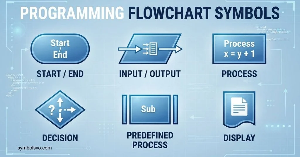
Programming flowcharts use standard flowchart shapes to represent algorithms before or alongside writing code.
Common symbols include:
- Terminator: Start or End
- Process: Calculation or instruction
- Decision: If/else condition
- Input/Output: Read or display data
- Flowline: Program sequence
- Connector: Joins separated parts of a diagram
- Predefined process: Calls a previously defined routine
Consider this simple algorithm:
Start
↓
Input: Enter age
↓
Decision: Is age 18 or older?
↙ Yes No ↘
Output: Adult Output: Minor
↓ ↓
End
The flowchart helps programmers check the logic before translating it into code.
Program Flowchart Symbols
Program flowcharts describe the sequence of instructions in a particular program or algorithm.
A typical program flowchart may include an input symbol for receiving data, process symbols for calculations, decision symbols for conditions, and output symbols for displaying results.
For example, a program that calculates an average could follow this sequence:
- Start.
- Input three numbers.
- Add the numbers.
- Divide the total by three.
- Display the average.
- End.
The calculation itself can be placed inside a process rectangle, while the numbers and result can be represented using input/output symbols.
Program flowcharts are particularly helpful when an algorithm contains several branches or repeated operations.
Logic Flowchart Symbols
Logic flowcharts focus on how conditions, rules, and decisions control a process. They are useful for explaining algorithms and business logic.
The diamond is the central symbol for branching logic. It can represent conditions such as:
- Is the user authorized?
- Is the amount greater than $100?
- Is the file available?
- Is the answer correct?
- Has the process finished?
A flowline connects the logic steps, while rectangles represent actions performed after a condition is evaluated.
For complex logic, keep each decision focused on one clear condition. This makes the diagram easier to follow and reduces confusing branches.
System Flowchart Symbols
System flowcharts show how information moves through a system. They can describe relationships between inputs, processes, storage, outputs, and other system components.
Common symbols include:
| Symbol | Typical role |
| Terminator | Start or end of the system flow |
| Input/Output | Data entering or leaving |
| Process | Data processing operation |
| Database | Stored information |
| Document | Printed or generated information |
| Display | Information presented on a screen |
| Flowline | Movement of data or control |
| Connector | Connection between diagram sections |
A system flowchart might show data entering through a user interface, being processed by an application, stored in a database, and returned to the user as an output.
System flowcharts can become detailed quickly, so clear labels and consistent connections are essential.
Workflow Chart Symbols
Workflow charts show how work moves between tasks, people, teams, or stages.
The most useful symbols are usually simple:
- Start/End: Marks the boundaries of the workflow.
- Process: Represents a task.
- Decision: Shows an approval, condition, or choice.
- Document: Shows a form, report, or other document.
- Flowline: Shows the next step.
- Database: Shows stored information.
For example, an employee leave workflow might be:
Start → Submit request → Manager reviews request → Approved?
If Yes, the workflow can move to Update leave record.
If No, it can move to Notify employee.
Workflow diagrams often benefit from swimlanes when several people or departments are involved. The symbols show what happens, while the lanes show who is responsible.
Manufacturing Process Flowchart Symbols
Manufacturing flowcharts map the movement of materials, products, inspections, and production steps.
Common symbols include process steps, decisions, inspections, storage, transportation, and delays. The exact notation can vary depending on the methodology being used.
A simplified manufacturing flow may look like:
Start → Receive raw materials → Inspect materials → Pass inspection? → Process materials → Assemble product → Final inspection → Package → End
A decision diamond can show whether materials pass inspection. A storage symbol can identify inventory, while process symbols can represent production operations.
Manufacturing diagrams are most useful when each step is specific. Instead of writing “Process item,” a clearer label might be “Cut sheet metal” or “Apply protective coating.”
Visio Flowchart Symbols
Microsoft Visio provides flowchart shapes that can be dragged onto a drawing page and connected to create diagrams. The exact available shapes depend on the diagram type and Visio template.
Common Visio flowchart shapes include:
- Start/End
- Process
- Decision
- Data
- Subprocess
- Document
- Database
- Connector
- Manual input
- Delay
- Display
Visio also supports specialized diagram templates and shape sets. When creating a diagram, choose a flowchart template that matches the type of process you are documenting.
The key benefit is consistency. Once the correct shapes are selected, connectors can be used to show how each step relates to the next.
Flowchart Symbols Explained
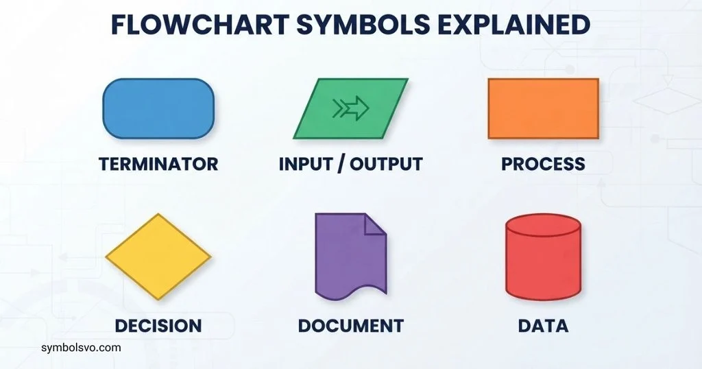
Flowchart symbols are easier to understand when you think of them as a visual language.
Shapes tell you what kind of step you are looking at. A rectangle usually means an action, while a diamond signals a decision.
Arrows tell you where to go next. They create the sequence and connect one part of the process to another.
Labels explain the specific action or condition. A rectangle labeled “Check inventory” is much more useful than a blank rectangle.
Branches show alternatives. A diamond can split a process into Yes/No, Pass/Fail, Approved/Rejected, or other clearly labeled paths.
The best flowcharts are not necessarily the ones with the most symbols. A good diagram uses only the symbols needed to communicate the process clearly.
Flowchart Symbols Guide
A simple way to choose the right flowchart symbol is to ask what you are trying to represent.
| If you want to show… | Use… |
| Beginning or ending | Terminator |
| An action or task | Process |
| A question or condition | Decision |
| Direction | Flowline |
| Data entering or leaving | Input/Output |
| Stored information | Database |
| A report or file | Document |
| A process defined elsewhere | Predefined process |
| A connection | Connector |
| A waiting period | Delay |
| A screen or visible result | Display |
| Manually entered data | Manual input |
For readable flowcharts, keep the direction consistent, usually from top to bottom or left to right. Give decisions clear labels, avoid unnecessary line crossings, and use short descriptions inside shapes.
If a diagram becomes too large, divide it into logical sections or use connectors to connect related areas. A flowchart should help the reader understand a process faster, not make the process harder to follow.
FAQ
What Is The Most Common Flowchart Symbol?
The rectangle is one of the most common flowchart symbols because it represents a process or action. The oval terminator, diamond decision, and arrow flowline are also used frequently.
What Does A Diamond Mean In A Flowchart?
A diamond represents a decision or condition. It usually creates two or more possible paths, such as Yes/No, True/False, or Approved/Rejected.
What Does A Rectangle Mean In A Flowchart?
A rectangle normally represents a process, task, operation, or action. For example, “Calculate total” can be written inside a process rectangle.
What Symbol Is Used For Start And End In A Flowchart?
A terminator is commonly used for the start and end of a flowchart. It is usually shown as an oval or rounded shape with labels such as “Start” and “End.”
How Do You Choose The Right Flowchart Symbol?
Choose the symbol based on what the step represents. Use a process shape for an action, a diamond for a decision, an input/output shape for data, and a terminator for the beginning or end.
Conclusion
Flow chart symbols provide a simple visual language for showing how a process works. The most familiar shapes include the terminator, process rectangle, decision diamond, input/output parallelogram, flowline, document, database, and connector.
Different types of flowcharts use these symbols for different purposes. Programming and logic diagrams focus on algorithms and conditions, while system, workflow, and manufacturing diagrams can show data, tasks, storage, people, materials, and production stages.
The best flowchart is clear, consistent, and easy to follow. Use standard symbols where practical, keep labels short, connect steps logically, and choose only the shapes that help explain the process.

I’m Daniel Brooks, a content creator and symbol enthusiast dedicated to researching the fascinating world of signs and symbols. I enjoy discovering the hidden meanings behind famous icons, emojis, historical emblems, and cultural symbols. Through my writing, I aim to provide trustworthy, well-researched, and reader-friendly information that helps people learn something new with every visit.
Books:
- The Complete Guide to World Symbols
- The Power of Universal Signs
 Mason Ellington
 Grace Whitmore