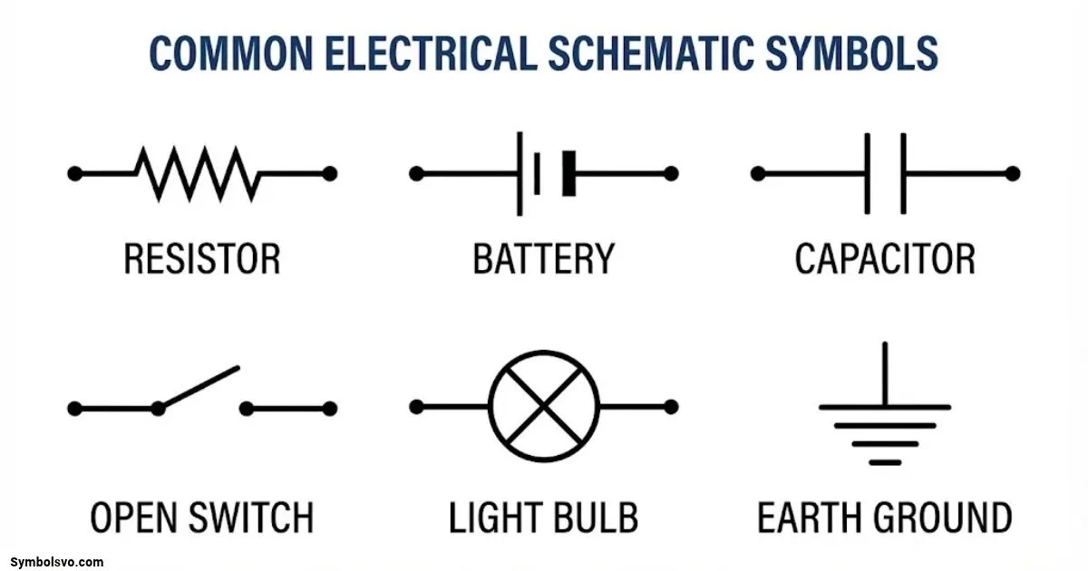
Electrical systems may contain dozens or even hundreds of components. Understanding how these components connect and work together becomes much easier when you know how to read their symbols. That’s where electrical schematic symbols come in. They provide a common visual language that helps electricians, engineers, technicians, and students understand electrical circuits without examining every physical component.
If you’re studying basic electronics, planning a home electrical installation, or troubleshooting an industrial control panel, recognizing electrical symbols is an essential skill. A resistor, capacitor, switch, battery, and motor each have a specific graphical representation that communicates their function within a circuit.
However, not every electrical drawing uses exactly the same symbol conventions. International projects commonly follow IEC practices, while North American drawings often use ANSI/IEEE conventions. Understanding these differences can prevent confusion when working with technical documents.
This guide explains common electrical symbols and their meanings, including their functions, applications, diagram types, and drawing standards. You’ll also learn how to read electrical schematics, recognize confusing symbols, and understand the abbreviations used in electrical engineering drawings.
What Are Electrical Schematic Symbols?
Electrical schematic symbols are standardized graphical representations of electrical and electronic components. They show how different parts of a circuit function and connect without displaying their actual physical appearance.
For example, a resistor doesn’t look like a zigzag line or a rectangle in real life. However, engineers use these shapes to represent its electrical function in a schematic diagram. Similarly, a battery symbol uses alternating long and short parallel lines to indicate electrical cells.
These symbols make complicated electrical systems easier to understand. Instead of drawing realistic pictures of every component, engineers use simple shapes, lines, and labels to explain the circuit.
An electrical schematic symbol generally communicates three important things:
- Component identity: Identifies the electrical device or component.
- Electrical function: Explains what the component does within the circuit.
- Connection points: Shows where wires or other components connect.
Why Are Electrical Symbols Used?
Electrical symbols make technical drawings shorter, clearer, and easier to interpret. They also help different professionals communicate using familiar graphical conventions.
Common reasons for using electrical symbols include:
- Circuit design: Engineers represent electrical components before building a circuit.
- Installation: Electricians use drawings to understand wiring connections and equipment locations.
- Troubleshooting: Technicians trace circuits to identify possible faults.
- Maintenance: Maintenance teams use existing drawings to understand equipment connections.
- Documentation: Companies maintain standardized electrical drawings for future reference.
- Communication: Engineers and technicians can understand circuit functions without relying on realistic component illustrations.
The main advantage is consistency. A properly prepared electrical drawing allows someone familiar with its conventions to understand the circuit even if they didn’t create it.
Electrical Schematic Symbols Chart: Common Symbols and Their Meanings
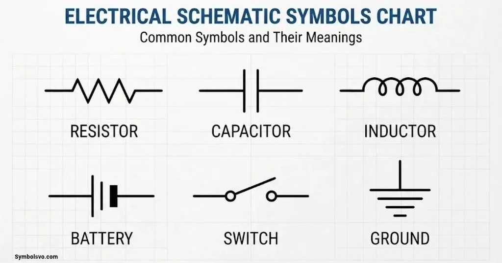
An electrical schematic symbols chart provides a quick reference for identifying components in circuit diagrams. Most charts organize symbols into categories based on their functions.
The following sections explain commonly used electrical symbols, their appearances, and what they represent.
Basic Electrical Circuit Symbols
Basic circuit symbols represent the wires, connections, terminals, and grounding points that form an electrical circuit. Without these elements, it’s difficult to understand how electricity travels between components.
| Electrical symbol | Common visual representation | Meaning and function |
| Electrical wire | Straight line | Represents a conductor connecting circuit components. |
| Connected wires | Intersecting lines with a filled dot | Indicates that conductors share an electrical connection. |
| Crossing wires | Crossing lines without a connection marker, depending on convention | Represents conductors that cross without joining. |
| Junction | Filled circular point | Identifies a connection between multiple conductors. |
| Terminal | Small open circle | Shows an electrical connection point. |
| Connector | Connector outline with terminals | Represents a detachable electrical connection. |
| Ground | Three decreasing horizontal lines | Indicates a circuit reference or grounding connection, depending on the symbol. |
| Earth ground | Protective earth symbol | Represents a connection to the earth for electrical safety. |
| Chassis ground | Chassis-ground symbol | Indicates a connection to a conductive equipment frame or chassis. |
| Open circuit | Broken conducting path | Indicates an interrupted electrical path. |
| Closed circuit | Continuous conducting path | Indicates a complete electrical connection. |
Understanding wire connections is especially important. Two lines crossing on a drawing don’t always indicate an electrical connection. Check for a junction dot, a T-junction, or another connection convention specified in the drawing legend.
Passive Electrical Component Symbols
Passive components influence voltage, current, and energy within a circuit. Unlike active semiconductor devices, they don’t provide electrical amplification through an external power supply.
Here are the most common passive electrical component symbols.
| Component | Common symbol appearance | Function |
| Resistor | Zigzag line in common US drawings or rectangle in IEC drawings | Limits current and produces a voltage drop. |
| Variable resistor | Resistor with a diagonal adjustment arrow | Allows resistance to change. |
| Potentiometer | Resistor with an adjustable contact | Provides an adjustable voltage or resistance. |
| Thermistor | Resistor symbol with a temperature marking | Changes resistance with temperature. |
| Photoresistor (LDR) | Resistor with arrows pointing toward it | Changes resistance according to light intensity. |
| Capacitor | Two parallel plates | Stores energy in an electric field. |
| Polarized capacitor | Capacitor plates with polarity marking | Stores electrical energy with specified polarity. |
| Variable capacitor | Capacitor with an adjustment arrow | Allows capacitance to change. |
| Inductor | Series of curved loops | Stores energy in a magnetic field. |
| Variable inductor | Inductor with an adjustment marking | Provides adjustable inductance. |
| Transformer | Two coupled coil symbols | Transfers electrical energy through electromagnetic induction. |
Resistor Symbol
A resistor controls the amount of current flowing through an electrical circuit. Its resistance is measured in ohms (Ω).
North American schematics traditionally represent a resistor using a zigzag line. IEC-style drawings generally use a rectangular symbol.
Resistors appear in:
- LED lighting circuits.
- Voltage divider networks.
- Electronic control boards.
- Signal processing circuits.
- Current-limiting applications.
For example, a resistor connected in series with an LED limits current and helps protect the LED from excessive electrical flow.
Capacitor Symbol
A capacitor stores electrical energy in an electric field. Its basic schematic symbol consists of two parallel plates.
Capacitors are commonly used for:
- Filtering electrical signals.
- Smoothing DC power supplies.
- Timing circuits.
- Noise reduction.
- Energy storage.
- Motor starting and running applications.
A polarized capacitor includes a positive and negative terminal. Installing it with incorrect polarity can damage the component or create a safety hazard.
Inductor Symbol
An inductor uses a coil of wire to store energy in a magnetic field. Its schematic symbol usually resembles a series of curved loops.
Inductors are common in:
- Power converters.
- Radio-frequency circuits.
- Filters.
- Switching power supplies.
- Electromagnetic equipment.
Their inductance is measured in henries (H).
Power Supply and Source Symbols
Power supply symbols identify where electrical energy enters a circuit. They help readers distinguish between alternating current, direct current, batteries, generators, and independent voltage or current sources.
| Component | Symbol description | Meaning |
| Battery | Alternating long and short parallel lines | Represents a battery made from one or more cells. |
| Single cell | One long and one short parallel line | Represents an individual electrochemical cell. |
| AC voltage source | Circle containing a sine-wave marking | Represents an alternating voltage source. |
| DC voltage source | Source symbol with polarity markings | Represents a direct voltage source. |
| Voltage source | Circle with polarity markings | Provides a specified voltage in a circuit model. |
| Current source | Circle with an arrow | Represents a specified current source. |
| Generator | Machine symbol, often identified by G | Converts mechanical energy into electrical energy. |
| Alternator | AC generator representation | Produces alternating electrical current. |
| Positive supply | Positive voltage label or supply connection | Identifies a positive electrical rail. |
| Negative supply | Negative voltage label or supply connection | Identifies a negative electrical rail. |
| Protective earth | Earth connection symbol | Identifies a protective grounding connection. |
AC and DC Power Symbols
Alternating current (AC) changes direction periodically. Household electrical distribution systems commonly use AC power.
Direct current (DC) flows with a consistent polarity. Batteries, many electronic circuits, and solar photovoltaic modules provide DC power.
These two types of electricity appear differently in electrical diagrams.
Common applications include:
- AC motors and generators.
- DC battery systems.
- Electronic power supplies.
- Solar panel installations.
- Battery charging systems.
- Industrial control equipment.
When reading a power supply symbol, check its voltage rating, polarity, and frequency where applicable. A symbol alone doesn’t tell you the full electrical specification.
Switch and Control Symbols
Switch symbols represent devices that open, close, or change electrical connections. They control the flow of electricity through a circuit.
| Switch type | Common designation | Function |
| Single-pole single-throw | SPST | Controls one circuit using one switching contact. |
| Single-pole double-throw | SPDT | Connects one common terminal to either of two terminals. |
| Double-pole single-throw | DPST | Controls two separate circuits together. |
| Double-pole double-throw | DPDT | Controls two circuits with two switching positions. |
| Normally open push button | NO | Remains open until operated. |
| Normally closed push button | NC | Remains closed until operated. |
| Selector switch | Selector | Allows selection between operating positions. |
| Limit switch | Limit | Changes contact position when mechanically activated. |
| Emergency stop | E-stop | Provides an emergency stopping control. |
| Changeover switch | Changeover | Transfers a connection between different circuits or sources. |
Normally Open and Normally Closed Contacts
These two terms are especially important when reading electrical control diagrams.
- Normally open (NO): The contact remains open in its normal, unoperated state.
- Normally closed (NC): The contact remains closed in its normal, unoperated state.
The word “normal” refers to the defined resting condition of the device. For a relay, this usually means the coil isn’t energized. For a push button, it generally means nobody is pressing it.
For example, a normally open push button can complete a circuit when pressed. A normally closed stop button can interrupt a control circuit when pressed.
Circuit Protection Symbols
Electrical protection devices help prevent damage caused by excessive current, short circuits, leakage currents, and abnormal electrical conditions.
| Component | Symbol description | Function |
| Fuse | Fuse element within a conductor path | Interrupts current when its element melts under specified fault conditions. |
| Circuit breaker | Mechanical switching and interruption symbol | Opens a circuit under defined fault or operating conditions. |
| Thermal overload relay | Thermal sensing and contact representation | Protects motors against sustained overload conditions. |
| Surge protection device (SPD) | Surge protection marking | Limits transient overvoltage at protected equipment. |
| Residual current device (RCD) | Differential current protection marking | Detects residual current and disconnects when its operating conditions are met. |
| Ground fault circuit interrupter (GFCI) | Ground-fault protection device marking | Provides protection against certain ground-fault conditions. |
| Protective relay | Relay and protection-function representation | Detects abnormal electrical conditions and initiates protective action. |
A fuse and a circuit breaker both provide overcurrent protection, but they work differently. A fuse must generally be replaced after operation, while a resettable circuit breaker can usually be restored after the fault has been investigated and corrected.
Never assume that a protective device makes an electrical circuit safe to touch. Isolation, verification, and proper safety procedures remain essential.
Semiconductor and Electronic Circuit Symbols
Semiconductor devices control the movement of electrical current through electronic circuits. They’re widely used in computers, power supplies, communication equipment, automation systems, and consumer electronics.
| Component | Common symbol features | Main function |
| Diode | Triangle-free diode symbol with anode and cathode markings | Allows current to flow primarily in one direction. |
| LED | Diode with outward-pointing arrows | Produces light when forward-biased. |
| Zener diode | Diode with a modified cathode line | Provides voltage regulation in suitable circuits. |
| Schottky diode | Diode with a modified cathode marking | Offers low forward voltage and fast switching. |
| Photodiode | Diode with inward-pointing arrows | Converts light into electrical current. |
| Bridge rectifier | Four-diode arrangement | Converts AC into pulsating DC. |
| NPN transistor | BJT symbol with an outward emitter arrow | Controls current using a base signal. |
| PNP transistor | BJT symbol with an inward emitter arrow | Controls current using a base signal. |
| FET | Field-effect transistor symbol | Controls current through an electric field. |
| MOSFET | Gate, drain, and source representation | Provides electronic switching or amplification. |
| SCR | Thyristor symbol with a gate connection | Controls current after triggering. |
| TRIAC | Bidirectional thyristor representation | Controls AC current in both directions. |
| Operational amplifier | Triangle with positive and negative inputs | Amplifies the difference between two input voltages. |
| Integrated circuit | Rectangle with labeled connection pins | Represents a complete electronic circuit inside one package. |
Diode and LED Symbols
A diode allows current to pass primarily in one direction. Its two terminals are called the anode and cathode.
An LED (light-emitting diode) works similarly but also produces light when current flows in the appropriate direction.
Common applications include:
- Indicator lights.
- Display panels.
- Rectifier circuits.
- Reverse-polarity protection.
- Lighting systems.
- Electronic signal circuits.
Transistor Symbols
A transistor controls electrical current and can work as an electronic switch or amplifier.
The two common such as of two minds junction transistor types are:
- NPN transistor.
- PNP transistor.
The emitter arrow helps distinguish them. In an NPN symbol, the arrow points outward. In a PNP symbol, it points inward.
MOSFETs and other field-effect transistors use different graphical representations because their internal operating principles differ.
Output and Electrical Load Symbols
Electrical loads consume electrical energy and convert it into light, heat, movement, sound, or another useful form.
| Component | Symbol description | Application |
| Light bulb | Circle with a cross or filament marking | Lighting and indication. |
| Indicator lamp | Lamp symbol with an indicator designation | Shows equipment status. |
| Electric motor | Circle containing M | Converts electrical energy into mechanical motion. |
| AC motor | Motor symbol with AC designation | Drives machinery using alternating current. |
| DC motor | Motor symbol with DC designation | Drives equipment using direct current. |
| Buzzer | Sound-producing device symbol | Produces an audible warning. |
| Bell | Bell-shaped device representation | Provides an audible signal. |
| Speaker | Speaker symbol | Converts electrical signals into sound. |
| Heater | Heating element representation | Converts electrical energy into heat. |
| Solenoid | Coil and mechanical actuator representation | Produces linear mechanical movement. |
| Electrical socket | Outlet or receptacle symbol | Provides an electrical connection for equipment. |
The same type of load can have different representations depending on the drawing. A motor in a single-line power diagram may appear as a simple circle marked M, while a motor control schematic may show additional terminals and control connections.
Electromechanical Component Symbols
Electromechanical devices combine electrical control with mechanical operation. They’re common in industrial control panels, machinery, automation systems, and motor circuits.
| Component | Symbol meaning | Main function |
| Relay | Coil and associated contacts | Operates electrical contacts using an electromagnetic mechanism. |
| Relay coil | Coil representation | Creates a magnetic field when energized. |
| NO relay contact | Normally open contact | Closes when the associated relay operates. |
| NC relay contact | Normally closed contact | Opens when the associated relay operates. |
| Contactor | Coil and main contacts | Switches electrical power to larger loads. |
| Auxiliary contact | Additional contact linked to a device | Provides control or status feedback. |
| Motor starter | Motor switching and protection arrangement | Controls and protects motor operation. |
| Overload contact | Thermal protection contact | Changes state when the associated overload device operates. |
A relay and its contacts may appear in different places on a schematic. Their matching reference designation connects them logically.
For example, a relay coil labeled K1 may control an NO contact also labeled K1. When the coil energizes, the associated contact changes state according to its design.
Measurement and Instrument Symbols
Measurement symbols identify instruments that monitor electrical quantities. They help technicians understand what a circuit measures and where measurement takes place.
| Instrument | Common identification | What it measures |
| Ammeter | A | Electric current. |
| Voltmeter | V | Voltage. |
| Ohmmeter | Ω | Electrical resistance. |
| Wattmeter | W | Electrical power. |
| Energy meter | kWh | Electrical energy consumption. |
| Multimeter | Meter symbol or instrument designation | Multiple electrical quantities. |
| Current transformer | CT | Reduces current to a measurable secondary value. |
| Potential transformer | PT or VT | Reduces voltage for measurement or protection. |
| Temperature sensor | Sensor designation | Temperature. |
| Pressure sensor | Sensor designation | Pressure. |
A current transformer is commonly used in power distribution and industrial measurement systems. Its ratio, such as 200:5, describes the relationship between primary and secondary current under its specified operating conditions.
A potential transformer performs a similar measurement function for voltage.
Communication and Signal Symbols
Communication and signal symbols appear in electronic, automation, and control diagrams. They represent devices and paths that carry information rather than simply supplying power.
Common examples include:
- Antenna: Transmits or receives electromagnetic signals.
- Microphone: Converts sound into an electrical signal.
- Speaker: Converts electrical signals into sound.
- Oscillator: Generates a periodic electrical signal.
- Pulse generator: Produces electrical pulses.
- Analog signal: Represents continuously varying information.
- Digital signal: Represents information using discrete states.
- Signal input: Identifies an incoming signal connection.
- Signal output: Identifies an outgoing signal connection.
- Signal ground: Provides a reference point for signal circuitry.
These symbols are particularly useful in communication equipment, automation controllers, and electronic circuit documentation.
Types of Electrical Diagrams and Their Symbols
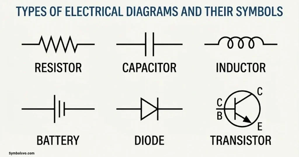
Not all electrical drawings communicate information in the same way. Some explain how a circuit works, while others show physical wiring or the arrangement of electrical equipment.
Understanding the different types of electrical diagrams helps you select the correct drawing for a particular task.
Electrical Schematic Diagram
An electrical schematic diagram shows the functional arrangement of electrical components and their connections. It focuses on how the circuit operates rather than the physical position of each component.
For example, a motor control schematic may include:
- Power supply.
- Stop and start push buttons.
- Contactor coil.
- Auxiliary contacts.
- Overload protection.
- Motor connections.
Engineers use schematic diagrams to design circuits, understand control logic, and troubleshoot equipment.
Electrical Wiring Diagram
A wiring diagram focuses on the actual electrical connections between components. It often includes terminal numbers, wire identification, connector details, and physical connection information.
Wiring diagrams are especially useful during installation and maintenance.
They can help electricians determine:
- Which terminal receives a particular wire.
- Where a conductor connects.
- How connectors are arranged.
- Which wires connect to a control device.
- How equipment terminals relate to one another.
Unlike a purely functional schematic, a wiring diagram may provide more information about the physical wiring arrangement.
Single-Line Diagram (SLD)
A single-line diagram represents a power system using simplified lines and symbols. One line can represent a three-phase circuit instead of showing all three phase conductors separately.
Single-line diagrams commonly appear in:
- Electrical substations.
- Industrial power distribution.
- Commercial buildings.
- Utility systems.
- Generator installations.
- Main distribution boards.
Common symbols include transformers, generators, circuit breakers, busbars, disconnect switches, and protective devices.
A single-line diagram helps engineers understand the overall power distribution arrangement without displaying every individual conductor.
Block Diagram
A block diagram represents major system functions using labeled blocks connected by lines or arrows.
For example, a power supply block diagram might contain:
AC input → Rectifier → Filter → Voltage regulator → DC output
Each block represents a major stage rather than every individual electrical component.
Block diagrams are useful for understanding the overall structure of complex electronic and electrical systems.
Pictorial Diagram
A pictorial diagram uses realistic illustrations of components instead of conventional schematic symbols.
It may show actual equipment shapes, wire positions, terminals, and connection arrangements.
Beginners often find pictorial diagrams easier to understand because they resemble the physical equipment. However, schematic diagrams usually provide a clearer representation of circuit logic.
Electrical Layout Diagram
An electrical layout diagram shows where electrical equipment and devices are positioned within a building or facility.
Residential and commercial layouts commonly identify:
- Lighting fixtures.
- Wall switches.
- Electrical outlets.
- Distribution boards.
- Ceiling fans.
- Smoke detectors.
- Equipment connection points.
These drawings support installation planning and help coordinate electrical work with architectural and structural layouts.
Control Circuit Diagram
A control circuit diagram explains how electrical equipment receives commands and changes operating states.
Common components include:
- Push buttons.
- Contactors.
- Relays.
- Limit switches.
- Overload contacts.
- Control transformers.
- Motor starters.
- Emergency stop devices.
Industrial electricians frequently use control diagrams to understand machine operation and diagnose faults.
Electrical Symbols and Their Meanings: Important Differences
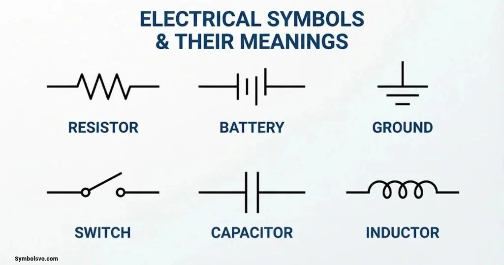
Some electrical symbols look similar even though they represent different functions. Understanding these differences is essential when reading unfamiliar schematics.
Ground vs. Earth Ground vs. Chassis Ground
These three grounding terms are related, but they don’t always mean the same thing.
| Grounding type | Purpose | Typical application |
| Circuit ground | Provides an electrical reference point | Electronic circuits and signal systems. |
| Earth ground | Connects an installation or protective system to earth | Electrical safety and grounding systems. |
| Chassis ground | Connects equipment circuitry to a conductive enclosure or frame | Industrial equipment and electronic devices. |
Circuit ground may serve as a voltage reference without being directly connected to earth. Protective earth, on the other hand, provides a safety connection intended to help protect against electric shock under fault conditions.
Never assume that every ground symbol represents an interchangeable connection.
AC vs. DC Electrical Symbols
AC and DC symbols identify different types of electrical supply.
| Feature | AC | DC |
| Full name | Alternating current | Direct current |
| Current direction | Changes periodically | Maintains a consistent polarity |
| Common source | Utility supply and alternators | Batteries and DC power supplies |
| Symbol convention | Sine-wave marking | Solid and dashed line convention or polarity marking |
| Common application | Household and industrial distribution | Electronics, batteries, and solar systems |
The actual voltage and frequency must be taken from the drawing or equipment specification.
Resistor vs. Variable Resistor vs. Potentiometer
A fixed resistor has a defined resistance value. A variable resistor allows its resistance to change through mechanical adjustment.
A potentiometer typically has three terminals and can function as an adjustable voltage divider.
These components may look similar in a drawing, but their functions differ.
Capacitor vs. Polarized Capacitor
A standard nonpolarized capacitor can generally operate with either terminal connected to a positive or negative potential within its ratings.
A polarized capacitor has designated positive and negative terminals. Its polarity must match the circuit requirements.
Electrolytic capacitors are common examples of polarized capacitors.
Fuse vs. Circuit Breaker
Both devices protect electrical circuits against excessive current, but their operating mechanisms differ.
A fuse uses a conductive element that melts when current exceeds its specified operating characteristics. A circuit breaker uses a switching mechanism to interrupt the circuit under specified conditions.
A fuse generally requires replacement after operation. A circuit breaker can usually be reset after inspection and correction of the fault.
Relay vs. Contactor
Relays and contactors both use control signals to operate electrical contacts.
However, contactors are generally designed for switching power circuits and larger electrical loads. Relays commonly handle control, signaling, and switching functions.
Their actual ratings and applications depend on the device specification.
How to Read Electrical Schematic Diagrams
Reading an electrical schematic becomes easier when you follow a consistent method. Instead of trying to identify every component at once, begin with the overall circuit and gradually examine its individual sections.
Start With the Diagram Title and Legend
First, identify the drawing type and its purpose.
The legend explains the symbols, abbreviations, and conventions used throughout the document.
Look for:
- Drawing title.
- Drawing number.
- Revision information.
- Applicable electrical standard.
- Symbol legend.
- Reference notes.
- Sheet numbers.
A drawing may include company-specific symbols. Always check its legend before interpreting unfamiliar markings.
Identify the Power Source
Find where electrical energy enters the circuit.
Look for batteries, AC supply connections, DC power supplies, generators, or transformers.
Then identify the relevant voltage and polarity information.
Understanding the source helps you establish the circuit’s operating conditions.
Recognize Electrical Components
Identify the main components and their functions.
For example, a basic electronic circuit might contain a battery, resistor, switch, and LED.
A motor control circuit could include a power source, contactor, overload relay, push buttons, and motor.
Look at both the symbol and its nearby identification label. The label often provides information that the symbol alone cannot communicate.
Follow Electrical Connections
Trace the conductors from the power source through the circuit.
Pay attention to:
- Junction dots.
- Crossing conductors.
- Terminal numbers.
- Wire numbers.
- Connector references.
- Ground connections.
- Sheet-to-sheet connections.
A small connection detail can change the meaning of an entire circuit.
Understand Circuit Operation
Once you’ve identified the components and connections, determine how the circuit operates.
For example, in a basic motor starter:
- The control supply provides electrical power.
- Pressing the start button energizes the contactor coil.
- The contactor’s main contacts close.
- The motor receives power.
- An auxiliary contact may maintain the control circuit.
- Pressing stop interrupts the control circuit and de-energizes the contactor.
This sequence demonstrates how individual symbols work together to represent an operating electrical system.
Understand Component Labels and Reference Designators
Reference designators identify individual components on electrical drawings.
Common examples include:
| Letter | Component |
| R | Resistor |
| C | Capacitor |
| L | Inductor |
| D | Diode |
| Q | Transistor |
| S | Switch |
| F | Fuse |
| K | Relay or contactor in many control drawings |
| T | Transformer |
| M | Motor |
| U | Integrated circuit |
| G | Generator in certain drawing conventions |
These letters are common conventions, not a universal identification system. Always verify the project’s applicable standard.
For example, R1 identifies one resistor, while R2 identifies another. The number distinguishes individual components of the same general type.
Follow Cross-References and Connection Labels
Large electrical drawings often spread one circuit across multiple pages.
Cross-references help you locate related components and connections.
Look for:
- Sheet references.
- Wire identification numbers.
- Terminal designations.
- Connector pin numbers.
- Relay contact references.
- Off-page connection labels.
These details prevent you from treating a multi-page electrical system as separate, unrelated circuits.
IEC vs. ANSI Electrical Schematic Symbols
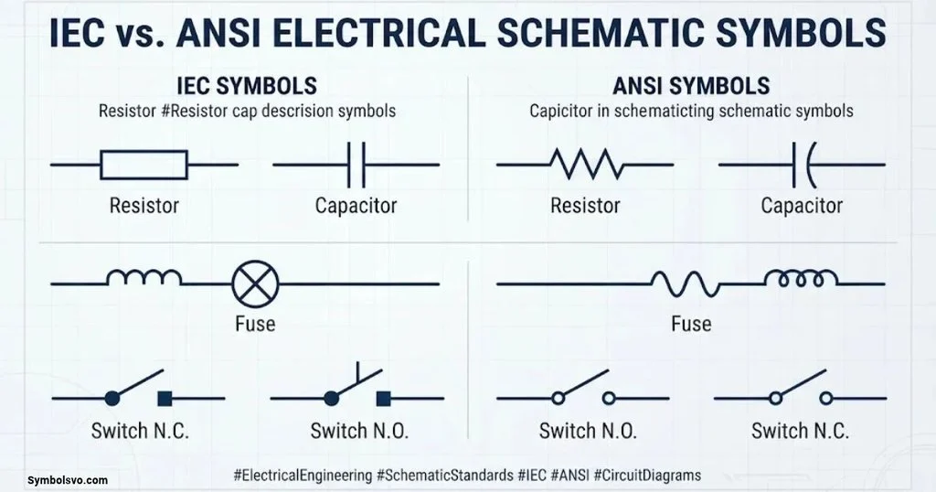
Electrical symbols follow established drawing conventions. Two important references are IEC 60617 and the North American electrical and electronic drawing conventions historically associated with ANSI Y32.2 and IEEE 315.
What Are IEC Electrical Symbols?
The International Electrotechnical Commission (IEC) develops international standards for electrical and electronic technologies.
IEC 60617 is the international graphical symbol database for diagrams. It covers symbols used in electrical engineering documentation, including conductors, components, switching devices, protection equipment, and measurement instruments.
IEC-style symbols are widely used in international engineering projects and equipment documentation.
What Are ANSI Electrical Symbols?
ANSI stands for the American National Standards Institute.
North American electrical and electronics drawings have historically used conventions associated with ANSI Y32.2 and IEEE Std 315.
These references describe graphical symbols and conventions for representing electrical and electronic components.
One well-known difference is the resistor symbol:
- Traditional North American representation: Zigzag line.
- IEC representation: Rectangle.
Key Differences Between IEC and ANSI Symbols
| Component | Common North American representation | Common IEC representation |
| Resistor | Zigzag line | Rectangle |
| Lamp | Circle with filament or cross | Circle with cross |
| Conductors | Lines with connection conventions | Lines with connection conventions |
| Ground | Grounding mark | Grounding mark |
| Capacitor | Parallel plates | Parallel plates |
| Diode | Diode with cathode bar | Diode with cathode bar |
| Transformer | Coupled coil representation | Coupled coil representation |
Not every symbol differs between the two systems. Many components use similar or identical graphical representations.
The drawing’s legend and stated standard should always take priority over assumptions based on appearance.
Why Electrical Symbol Standards Matter
Standardization helps electrical professionals interpret drawings consistently.
Its main benefits include:
- Reducing confusion between different drawing conventions.
- Improving technical communication.
- Supporting international engineering projects.
- Making maintenance documentation easier to understand.
- Improving consistency across electrical design documents.
One important distinction: IEC 60617 concerns graphical symbols for diagrams. Equipment markings and other technical conventions may fall under different standards, so don’t treat every electrical marking as part of the same symbol database.
Electrical Schematic Symbols Used in Different Applications
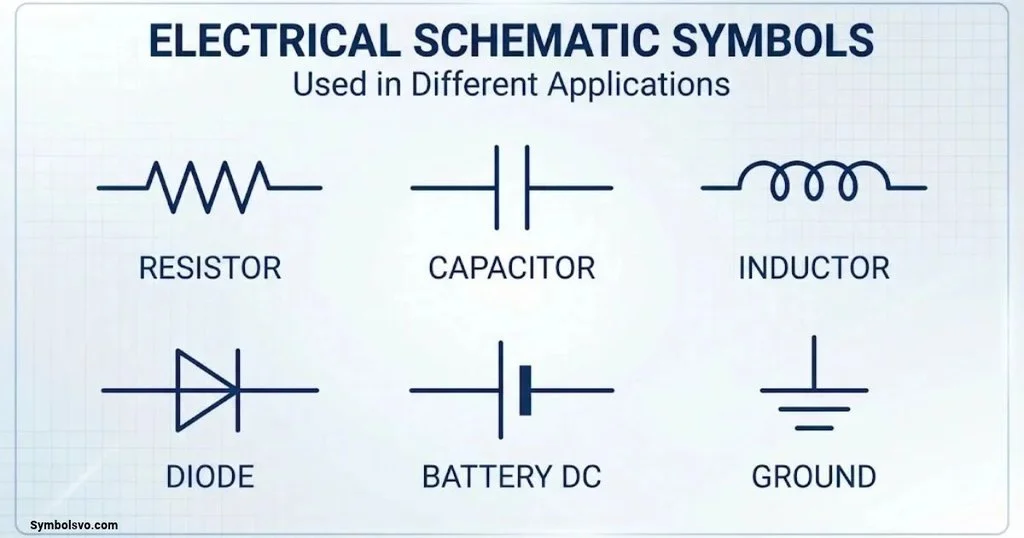
Electrical symbols appear in residential, commercial, industrial, and electronic systems. Their purpose remains similar, but the types of components and drawings depend on the application.
Residential Electrical Symbols
Residential electrical drawings show the arrangement of equipment in homes and other living spaces.
Common symbols represent:
- Light fixtures.
- Wall switches.
- Electrical outlets.
- Ceiling fans.
- Circuit breakers.
- Distribution panels.
- Smoke detectors.
- Lighting control points.
These symbols help electricians understand the location and connection requirements of electrical equipment.
For example, a residential lighting layout may show a ceiling light connected to a wall switch. The layout identifies their positions, while a wiring diagram explains the actual electrical connections.
Industrial Electrical Symbols
Industrial electrical drawings represent machinery, control panels, power equipment, and automation systems.
Common industrial symbols include:
- Electric motors.
- Contactors.
- Relays.
- Overload protection.
- Push buttons.
- Limit switches.
- Variable frequency drives.
- Transformers.
- Circuit breakers.
- Programmable logic controllers (PLCs).
Motor control diagrams are particularly important in industrial environments because they explain how machinery starts, stops, and responds to control signals.
Power Distribution Symbols
Power distribution drawings represent the movement of electrical energy through a facility or electrical network.
Common components include:
- Transformers.
- Generators.
- Busbars.
- Circuit breakers.
- Disconnect switches.
- Current transformers.
- Potential transformers.
- Protective relays.
- Grounding connections.
A single-line diagram is commonly used to represent these systems because it simplifies complex three-phase power networks.
Electronic Circuit Symbols
Electronic circuit diagrams use symbols for components that process, control, or amplify electrical signals.
Common examples include:
- Resistors.
- Capacitors.
- Inductors.
- Diodes.
- Transistors.
- Integrated circuits.
- Operational amplifiers.
- Logic gates.
- Signal generators.
These symbols appear in consumer electronics, computers, communication equipment, and embedded systems.
Renewable Energy and Solar Electrical Symbols
Solar electrical drawings represent the components that connect photovoltaic modules to batteries, inverters, and electrical distribution systems.
Common elements include:
- Solar photovoltaic modules.
- DC disconnect switches.
- String fuses.
- Combiner boxes.
- Charge controllers.
- Battery banks.
- Inverters.
- AC distribution boards.
- Grid connection points.
- Protective grounding connections.
A solar single-line diagram helps installers and engineers understand how the DC and AC sections connect.
It also identifies important protection and isolation equipment. The actual installation must follow applicable electrical codes, equipment instructions, and safety requirements.
Electrical Symbol Reference Designators and Abbreviations
Electrical drawings use letters, numbers, and abbreviations to identify components and explain technical information.
Understanding these labels makes diagrams easier to interpret.
Common Electrical Drawing Abbreviations
| Abbreviation | Full form | Meaning |
| AC | Alternating Current | Current that periodically changes direction. |
| DC | Direct Current | Current with consistent polarity. |
| GND | Ground | Electrical reference connection. |
| PE | Protective Earth | Safety grounding conductor. |
| NO | Normally Open | Contact open in its normal state. |
| NC | Normally Closed | Contact closed in its normal state. |
| CT | Current Transformer | Instrument transformer for current measurement. |
| PT | Potential Transformer | Instrument transformer for voltage measurement. |
| VT | Voltage Transformer | Another designation for a voltage instrument transformer. |
| CB | Circuit Breaker | Protective switching device. |
| SPD | Surge Protection Device | Device that limits transient overvoltage. |
| VFD | Variable Frequency Drive | Controls motor speed through electrical frequency and voltage. |
| PLC | Programmable Logic Controller | Industrial control computer. |
| MCC | Motor Control Center | Assembly of motor control equipment. |
| RCD | Residual Current Device | Detects residual current. |
| GFCI | Ground Fault Circuit Interrupter | Provides ground-fault protection. |
Understanding Electrical Ratings and Labels
Electrical drawings often include numerical values alongside component symbols.
These values provide information that helps identify the correct equipment and understand circuit requirements.
Common ratings include:
- Voltage (V): Electrical potential difference.
- Current (A): Electrical current capacity or operating current.
- Resistance (Ω): Opposition to current flow.
- Capacitance (F): Ability to store electrical charge.
- Inductance (H): Ability to store energy in a magnetic field.
- Power (W): Rate of electrical energy transfer.
- Frequency (Hz): Number of AC cycles per second.
- Wire size: Conductor dimensions, commonly specified using AWG or metric cross-sectional area.
For example, a resistor marked 1 kΩ has a nominal resistance of 1,000 ohms. A motor marked 5 kW has a rated mechanical or electrical power specification that must be interpreted according to its nameplate and documentation.
Don’t confuse a component’s reference designation with its rating. R1 identifies a resistor, while 1 kΩ describes its resistance.
How to Create Electrical Schematic Diagrams
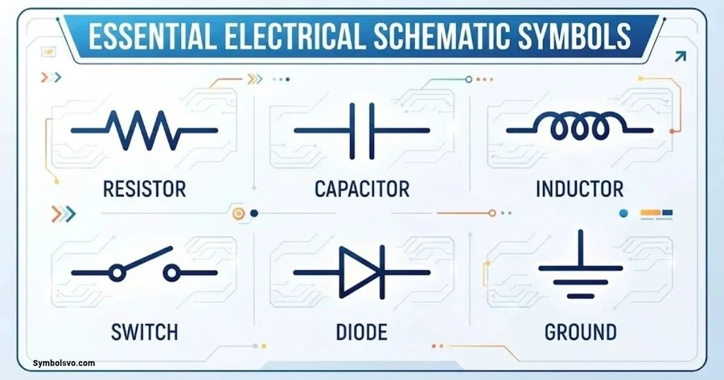
Creating an accurate electrical schematic requires more than placing symbols on a page. The drawing must communicate the intended circuit operation and identify its components and connections clearly.
Plan the Electrical Circuit
Begin by identifying what the circuit needs to accomplish.
Determine:
- The circuit’s purpose.
- Required power supply.
- Main electrical components.
- Control requirements.
- Protection requirements.
- Input and output connections.
A clear plan prevents unnecessary complexity during drawing.
Select the Correct Electrical Symbols
Choose symbols that match the components and applicable drawing standard.
For example, select the correct resistor representation, capacitor type, switch contact, and grounding symbol.
Use consistent conventions throughout the drawing. If the project requires a specific symbol library, follow it.
Draw the Electrical Connections
Arrange components so that the circuit’s operating logic is easy to follow.
Add conductors, junctions, terminals, and connection labels.
Avoid unnecessary line crossings. Where crossings are unavoidable, use clear connection conventions.
Add Component Labels and Ratings
Identify each component using reference designators and relevant technical values.
Include voltage ratings, current ratings, component values, wire numbers, and terminal identifiers when required.
Review and Verify the Diagram
Before releasing the drawing, check:
- Component symbols.
- Electrical connections.
- Terminal numbers.
- Wire identification.
- Power supply ratings.
- Protection arrangements.
- Cross-references.
- Drawing legend.
- Applicable standards.
For safety-critical or regulated installations, the drawing should receive the appropriate technical review before use.
Electrical Schematic Drawing Software
Electrical CAD software helps engineers create, edit, organize, and maintain electrical drawings.
Different tools serve different purposes. Some focus on industrial control systems, while others specialize in electronic circuit design.
AutoCAD Electrical
AutoCAD Electrical is a specialized electrical design tool within Autodesk’s CAD ecosystem.
Common features include:
- Electrical schematic creation.
- Component symbol libraries.
- Wire numbering.
- Circuit documentation.
- Cross-referencing.
- Electrical project organization.
It’s particularly useful for professional electrical control drawings.
QElectroTech
QElectroTech is an open-source application for creating electrical diagrams.
Its main features include:
- Electrical symbol collections.
- Schematic drawing tools.
- Component management.
- Technical documentation.
- Custom symbol creation.
It’s a practical option for students, technicians, and users who want an accessible electrical drawing application.
KiCad
KiCad is an open-source electronics design suite.
It supports:
- Electronic schematic capture.
- Component symbol libraries.
- PCB layout design.
- Electrical rule checking.
- Schematic-to-PCB workflows.
It’s especially useful for electronic circuit design rather than general building wiring layouts.
Microsoft Visio
Microsoft Visio supports general diagram creation, including electrical and technical diagrams.
Users can create basic circuit illustrations, connection diagrams, and equipment layouts.
However, it’s not a direct replacement for specialized electrical CAD tools when advanced electrical documentation is required.
ProfiCAD
ProfiCAD focuses on electrical and electronic diagram creation.
Its capabilities include:
- Electrical schematic drawing.
- Wiring diagrams.
- Symbol libraries.
- Component identification.
- Technical drawing exports.
It’s suitable for users who need a relatively straightforward electrical drawing workflow.
Choosing the Right Electrical Drawing Software
Consider the type of diagram you need before selecting a tool.
| Software | Best suited for | Main strength |
| AutoCAD Electrical | Industrial electrical design | Professional electrical documentation |
| QElectroTech | Electrical schematics | Open-source symbol libraries |
| KiCad | Electronic circuit design | Schematic and PCB integration |
| Microsoft Visio | General technical diagrams | Flexible diagram creation |
| ProfiCAD | Electrical and wiring diagrams | Simple electrical drawing workflow |
The right choice depends on project complexity, required standards, licensing, and the type of electrical documentation you’re preparing.
Common Mistakes When Reading Electrical Schematic Symbols
Even experienced technicians can misinterpret drawings when they overlook important details. Beginners should pay particular attention to the following mistakes.
Confusing Similar Electrical Symbols
Some symbols share similar shapes but perform different functions.
For example, a fixed resistor, variable resistor, and potentiometer may look related. However, their adjustment mechanisms and circuit applications differ.
Always consider the component label and its position within the circuit.
Ignoring the Electrical Diagram Legend
A drawing legend explains the conventions used in a particular project.
Ignoring it can lead to incorrect assumptions about symbols, connections, and abbreviations.
This becomes especially important when working with older drawings or equipment from international manufacturers.
Misreading Wire Connections
Crossing lines don’t necessarily indicate connected conductors.
Check for junction markers and follow the drawing’s connection conventions. Missing one connection can completely change your understanding of the circuit.
Ignoring Component Ratings
A symbol tells you what type of component appears in the circuit, but it doesn’t necessarily tell you its operating limits.
Read the accompanying ratings and equipment specifications.
A circuit breaker, for example, may have different voltage, current, and interrupting ratings. These values are essential when evaluating its suitability.
Mixing IEC and ANSI Conventions
Never assume every drawing uses the same symbol system.
Check the applicable standard and project legend before interpreting or modifying a drawing.
Consistency matters, particularly when multiple engineering teams work on the same electrical project.
Why Electrical Schematic Symbols Are Important
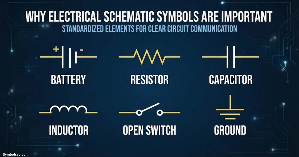
Electrical schematic symbols support almost every stage of electrical design, installation, operation, and maintenance.
Simplify Complex Electrical Circuits
A complicated electrical system may contain hundreds of components and connections.
Symbols allow engineers to represent these elements using a compact and organized drawing.
This makes it easier to understand the overall circuit structure.
Improve Electrical Installation
Electricians use electrical drawings to identify components, terminals, and wiring connections.
Accurate symbols help reduce confusion during installation and support proper equipment connections.
Make Electrical Troubleshooting Easier
Technicians can follow electrical paths, identify control devices, and locate protection components.
For example, a motor control schematic can help a technician trace why a contactor isn’t energizing. The problem may involve a stop button, overload contact, control fuse, or control supply.
Support Electrical Maintenance
Electrical drawings provide useful documentation for equipment inspection, repairs, and replacement.
When a technician understands the schematic, it’s easier to identify related components and understand how equipment should operate.
Improve Communication Between Professionals
Standardized electrical symbols provide a shared technical language.
Engineers, electricians, maintenance technicians, and equipment manufacturers can use the same drawing conventions to explain complex systems.
This improves coordination and reduces misunderstandings during technical work.
Frequently Asked Questions About Electrical Schematic Symbols
What Are Electrical Schematic Symbols?
Electrical schematic symbols are graphical representations of electrical and electronic components. They show component functions and connections within a circuit diagram. Common examples include resistors, capacitors, switches, batteries, motors, and circuit breakers.
What Are the Most Common Electrical Schematic Symbols?
Common electrical symbols include:
- Resistor.
- Capacitor.
- Inductor.
- Battery.
- Ground.
- Switch.
- Fuse.
- Circuit breaker.
- Diode.
- LED.
- Transformer.
- Relay.
- Motor.
- Generator.
These symbols appear in many electrical and electronic drawings.
What Do Electrical Symbols Mean in a Circuit Diagram?
Electrical symbols identify individual components and their roles within a circuit. A resistor limits current, a capacitor stores electrical energy, and a switch controls electrical connections. Lines represent conductors, while connection markers show where conductors join.
What Is the Difference Between Electrical Symbols and Wiring Symbols?
Electrical schematic symbols represent component functions and circuit relationships. Wiring symbols provide information about physical electrical connections, terminals, connectors, and conductors.
A schematic emphasizes how a circuit operates, while a wiring diagram often provides more installation-related details.
How Do You Read Electrical Schematic Symbols?
Start by identifying the drawing type and checking its legend. Then locate the power source, recognize the components, follow electrical connections, and examine reference designators. Finally, trace the circuit to understand how its different sections work together.
What Is the Symbol for a Resistor?
A resistor traditionally appears as a zigzag line in many North American electrical drawings. IEC-style schematics generally represent it as a rectangle. Both symbols represent a component that provides electrical resistance.
What Is the Electrical Symbol for a Capacitor?
A basic capacitor appears as two parallel plates with connections extending from opposite sides. A polarized capacitor includes additional polarity identification to distinguish its positive and negative terminals.
What Is the Electrical Symbol for a Battery?
A battery is represented by alternating long and short parallel lines. Each long-short pair represents a cell. A battery symbol can contain multiple pairs to represent a multi-cell battery.
What Does the Ground Symbol Mean?
A ground symbol identifies an electrical reference or grounding connection. Its exact meaning depends on the symbol type and drawing convention. Circuit ground, protective earth, and chassis ground have different purposes and shouldn’t automatically be treated as interchangeable.
What Is the Difference Between AC and DC Symbols?
AC represents alternating current, which periodically changes direction. DC represents direct current, which maintains consistent polarity. AC sources commonly use a sine-wave marking, while DC supply markings often use a solid line above a dashed line or explicit positive and negative labels.
What Does NO and NC Mean in Electrical Diagrams?
NO means normally open, while NC means normally closed. These terms describe the contact’s normal, unoperated state. An NO contact closes when operated, while an NC contact opens when operated.
What Is the Difference Between a Schematic and a Wiring Diagram?
A schematic diagram shows how electrical components function and connect logically. A wiring diagram focuses more on actual conductor connections, terminals, and wiring arrangements. Both are useful, but they serve different documentation purposes.
What Are IEC and ANSI Electrical Symbols?
IEC symbols follow international conventions associated with IEC 60617. ANSI/IEEE conventions have historically guided electrical and electronic drawing practices in North America. Some symbols look identical, while others, such as the resistor, have recognizable differences.
Are Electrical Schematic Symbols Universal?
No. Many electrical symbols are widely recognized, but their graphical representations can vary between standards, industries, and organizations. Always consult the applicable standard and drawing legend when interpreting an unfamiliar diagram.
Where Can I Find an Electrical Schematic Symbols Chart?
Electrical schematic symbols charts are commonly included in electrical engineering textbooks, technical manuals, CAD symbol libraries, equipment documentation, and electrical drafting references. Choose a chart that identifies its applicable standard and explains each symbol’s function.
What Software Is Used to Draw Electrical Schematics?
Common tools include AutoCAD Electrical, QElectroTech, KiCad, ProfiCAD, and Microsoft Visio. The best option depends on whether you’re creating industrial electrical drawings, electronic schematics, wiring diagrams, or general technical illustrations.
Can Beginners Learn to Read Electrical Diagrams?
Yes. Beginners can start with basic circuit symbols such as wires, resistors, capacitors, batteries, switches, and ground connections. Once they understand these components, they can progress to wiring diagrams, control circuits, and industrial electrical schematics.
Why Are Standardized Electrical Symbols Important?
Standardized symbols make electrical drawings easier to understand and share. They improve communication, support consistent documentation, reduce ambiguity, and help electrical professionals interpret circuits across different projects.
Conclusion
Electrical schematic symbols make complex electrical systems easier to understand, design, and maintain. By learning the meanings of common components, connection markings, power sources, and control devices, you can interpret electrical drawings with greater confidence.
Start with basic circuit symbols such as resistors, capacitors, batteries, switches, and grounding connections. Then move on to semiconductor devices, protective equipment, relays, motors, and industrial control symbols.
It’s equally important to understand the differences between schematic diagrams, wiring diagrams, and single-line diagrams. Each drawing communicates specific information, and the correct interpretation depends on its purpose and applicable standards.
Most importantly, never rely on a symbol’s appearance alone when interpreting an unfamiliar drawing. Check the legend, reference designators, equipment ratings, and relevant documentation. These details turn a collection of graphical marks into a clear representation of how an electrical system works.

Mason Ellington is a creative and dedicated Content Writer and Symbols Expert with a passion for words, communication, and symbolic meanings. He specializes in crafting engaging, informative, and well-structured content while exploring the deeper meanings and interpretations behind symbols. With a creative mindset and attention to detail, Mason transforms ideas into meaningful content that informs, inspires, and connects with readers. His expertise combines powerful storytelling, clear communication, and a deep understanding of symbolism.
 Daniel Brooks
 Nathan Holloway