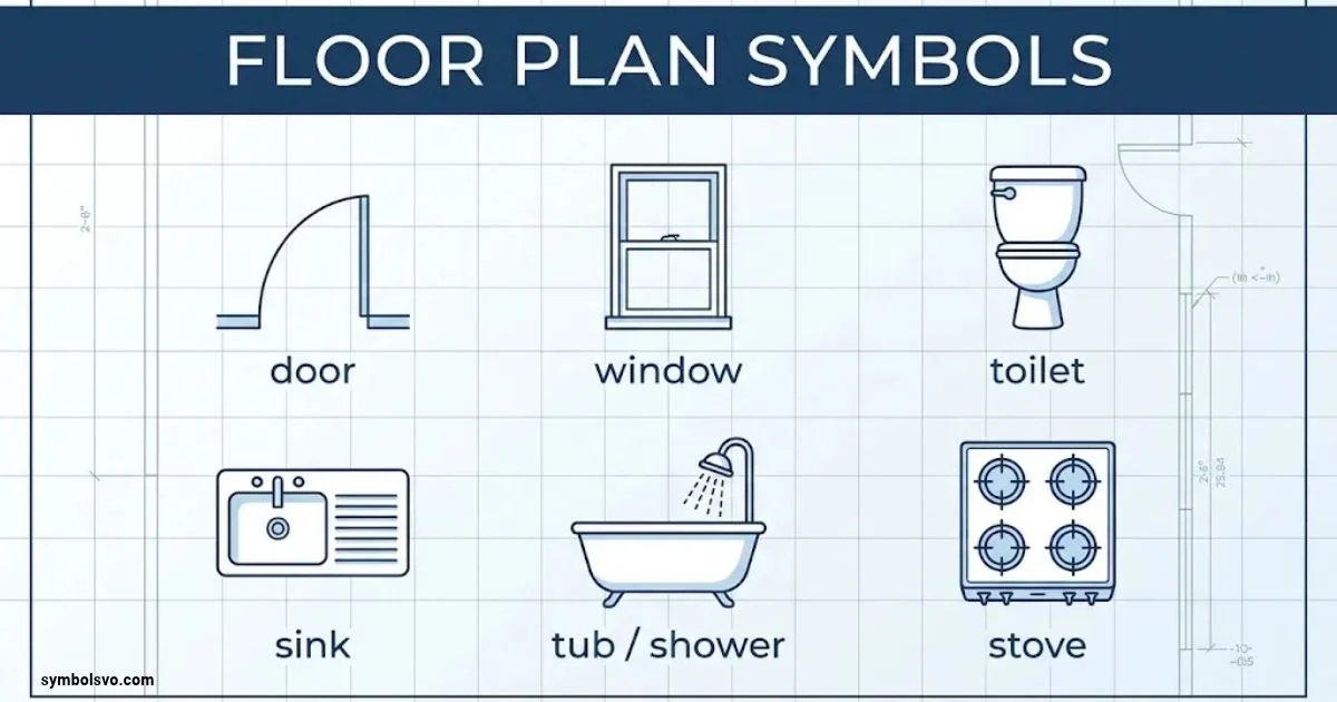
A floor plan can look like a maze of lines, shapes, numbers, and abbreviations until you understand what each mark represents. A simple rectangle might show a room, a curved line could indicate a door swing, and a small circle or cross may identify an electrical fixture. These details help architects, builders, contractors, and homeowners understand how a building is designed.
Floor plan symbols make architectural drawings easier to read. They show walls, doors, windows, stairs, furniture, plumbing fixtures, electrical points, and many other building features. Once you learn the common symbols and drawing conventions, you can understand a home’s layout without guessing what every line means.
This guide explains the most common floor plan symbols and their meanings, including architectural annotations, electrical marks, plumbing fixtures, dimensions, and construction abbreviations. You’ll also learn how to read a floor plan step by step and avoid common mistakes when interpreting building drawings.
What Are Floor Plan Symbols?
Floor plan symbols are simplified graphic marks used in architectural drawings to represent physical features, building components, and design information. Instead of drawing every object exactly as it would appear in real life, architects use familiar shapes and lines to communicate the layout clearly.
For example, a door may appear as a straight line with a quarter-circle arc. The line represents the door panel, while the arc shows the direction and space needed for it to swing open. A window often appears as one or more thin lines inside a wall.
These symbols help different people work from the same drawing. An architect can communicate the design, a contractor can understand the construction requirements, and a homeowner can see how rooms connect.
Why Are Architectural Floor Plan Symbols Important?
A floor plan does more than show where rooms sit. It communicates how a building works.
Understanding architectural drawing symbols helps you:
- Understand room layouts: Identify bedrooms, bathrooms, kitchens, hallways, and other spaces.
- Recognize building components: Distinguish walls, doors, windows, columns, and stairs.
- Plan furniture placement: See how much usable space a room offers.
- Locate utilities: Identify electrical outlets, switches, lights, plumbing fixtures, and ventilation points.
- Understand construction details: Follow dimensions, material patterns, section references, and elevation markers.
- Avoid costly mistakes: Spot possible layout conflicts before construction or renovation begins.
A clear floor plan also helps you compare properties. You can check whether a bedroom has enough space for a bed, whether a bathroom door opens into a narrow passage, or whether the kitchen connects conveniently to the dining area.
What Information Does a Floor Plan Show?
A typical architectural floor plan may include:
| Drawing element | What it communicates |
| Walls and partitions | Room boundaries and building divisions |
| Doors and windows | Openings, access, and natural light |
| Stairs | Changes in floor level and vertical circulation |
| Furniture symbols | Approximate furniture placement and room use |
| Plumbing fixtures | Toilets, sinks, showers, and tubs |
| Electrical symbols | Lights, switches, outlets, and related devices |
| Dimensions | Room sizes, wall lengths, and distances |
| Room labels | Names and intended uses of spaces |
| Reference markers | Connections to sections, elevations, and details |
Not every floor plan includes all these elements. A simple real estate plan may show only the rooms, openings, and basic dimensions. A construction drawing usually contains more technical information.
Common Floor Plan Symbols and Their Meanings
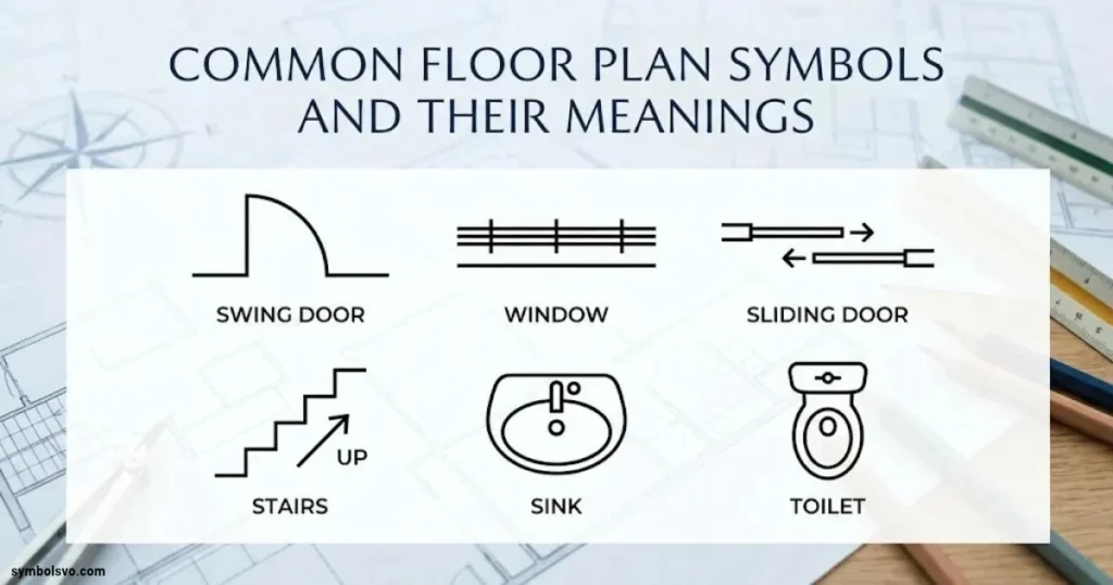
The most useful way to learn common floor plan symbols is to group them by function. Architectural drawings generally use different symbol families for walls, openings, furniture, fixtures, and building services.
The examples below explain common conventions. Their exact appearance can change between drawing sets, software libraries, and regional practices, so always check the project’s symbol legend.
Wall Symbols in Floor Plans
Walls define rooms, separate spaces, and support the building where required. On a floor plan, they usually appear as parallel lines, thick bands, or filled shapes.
| Wall symbol or appearance | Meaning | What to look for |
| Two thick parallel lines | Common wall representation | Often indicates a substantial wall assembly |
| Two thin parallel lines | Lightweight partition | May represent a non-load-bearing interior wall |
| Dark or filled wall band | Wall shown in section or cut | May distinguish walls cut by the plan view |
| Dashed wall lines | Overhead or hidden feature | Could show a wall or element above the cut plane |
| Heavy square or rectangle | Column or structural support | Check structural drawings for its exact role |
Exterior walls often appear thicker than interior partitions because they may contain insulation, cladding, structural materials, or multiple layers. However, line thickness alone does not prove whether a wall is load-bearing.
A load-bearing wall transfers structural loads to the foundation or another supporting element. A partition wall generally divides interior spaces without carrying the main building loads. You should never decide whether a wall can be removed based only on its appearance in a basic floor plan. Consult the structural drawings or a qualified professional.
Door Symbols and Their Meanings
Doors are among the easiest floor plan symbols to recognize. A typical hinged door appears as a straight line connected to a curved arc.
| Door symbol | Meaning | Common use |
| Line with quarter-circle arc | Single hinged door | Bedrooms, bathrooms, offices |
| Two door leaves with arcs | Double hinged door | Main entrances, large rooms |
| Two parallel panels | Sliding door | Patios, closets, room dividers |
| Door panel disappearing into wall | Pocket door | Bathrooms and compact spaces |
| Multiple folding panels | Bi-fold door | Closets and storage areas |
| Door with an exterior threshold | Exterior entrance | Main doors and garden access |
The curved arc represents the door’s swing direction. It helps you see which side the door opens toward and how much floor space it uses.
This detail matters when planning furniture. A door that swings into a bedroom may interfere with a wardrobe or bedside table. A bathroom door may also need enough clearance for safe and comfortable access.
Look for door tags such as D1, D2, or D-101. These labels usually connect the plan to a door schedule that lists dimensions, materials, hardware, fire ratings, and other specifications.
Window Symbols in Floor Plans
Windows usually appear as thin lines placed within an exterior or interior wall opening. Their appearance depends on the window type and the level of detail in the drawing.
| Window symbol | Meaning | Description |
| Two or three thin lines in a wall | Basic window | Shows a window opening in plan view |
| Lines with an opening arc | Casement window | Indicates a hinged window |
| Parallel sliding panels | Sliding window | Shows panels that move horizontally |
| Multiple sections in one opening | Multi-panel window | Often used for wider openings |
| Angled or projecting window shape | Bay window | Extends outward from the wall |
| Small window tag | Window identification | Links to a window schedule |
A window symbol may not show its full height, frame material, glazing type, or exact opening mechanism. Those details often appear in elevations, schedules, or window detail drawings.
For example, a plan may identify a window as W03. The window schedule may then explain that it is a particular width and height, uses a specific frame material, and includes a certain glazing specification.
Stair Symbols and Floor Level Indicators
Stairs connect different levels of a building. On a floor plan, they typically appear as a sequence of parallel lines representing individual steps.
| Symbol or label | Meaning |
| Repeated parallel lines | Stair treads or steps |
| UP | Direction toward the higher floor |
| DN | Direction toward the lower floor |
| Directional arrow | Indicates the direction of travel |
| Landing rectangle | Flat area between stair flights |
| Break line | Indicates that part of the stair continues beyond the plan cut |
A stair arrow is particularly important. It helps you understand whether the drawing shows the lower or upper part of a staircase and how the stair connects to another floor.
A stair landing provides a level area between flights or at the top and bottom of a stair. Its dimensions and arrangement matter for circulation and safety.
When reviewing stairs, check the architectural plan alongside the section drawing. The section provides a side view that can clarify stair height, floor-to-floor distance, headroom, and the relationship between landings.
Furniture Symbols in Floor Plans
Furniture symbols help show how a room may function. They are usually drawn from above, using simplified outlines rather than realistic illustrations.
| Furniture symbol | Typical meaning |
| Rectangle with pillows | Bed |
| Long rectangle with cushions | Sofa or couch |
| Small square or rectangle | Side table |
| Large rectangle with chairs | Dining table |
| Desk with chair | Workstation |
| Long narrow rectangle | Wardrobe or cabinet |
| Small circular shape | Round table or stool |
| Rectangle with internal divisions | Storage unit or shelving |
Furniture symbols are useful when assessing room layout and space planning. They help you estimate whether a room can comfortably fit the furniture shown.
However, furniture on a floor plan may be illustrative rather than a final specification. A sofa symbol, for example, may show the approximate footprint without identifying the exact model or dimensions.
Before purchasing furniture or finalizing a layout, compare the drawing’s scale and dimensions with the actual product measurements.
Bathroom and Plumbing Symbols
Bathroom symbols identify plumbing fixtures and help show how a wet area is arranged. They are important for understanding fixture locations, circulation, and plumbing coordination.
| Symbol | Meaning | Typical location |
| Oval or rounded bowl shape | Toilet | Bathroom or powder room |
| Small basin shape | Washbasin or sink | Bathroom |
| Long rectangular fixture | Bathtub | Full bathroom |
| Square or rectangular enclosure | Shower | Bathroom or wet room |
| Small fixture beside toilet | Bidet | Some residential bathrooms |
| Floor drain marker | Drain outlet | Shower or wet area |
| WH | Water heater | Utility area or service space |
A toilet symbol often includes a bowl shape and a smaller tank shape. A washbasin may appear as a rectangle or oval with a small drain mark. A shower can appear as a square enclosure with a drain or showerhead indication.
The plumbing layout can affect the cost and complexity of a project. Grouping bathrooms, kitchens, and utility spaces near shared plumbing routes may simplify installation, although the final arrangement depends on structural and engineering requirements.
Kitchen and Appliance Symbols
Kitchen floor plans show the arrangement of cabinets, worktops, sinks, and appliances. These symbols help you understand the kitchen’s working area and available circulation space.
| Symbol or abbreviation | Meaning |
| REF or REFR | Refrigerator |
| DW | Dishwasher |
| R or RANGE | Cooking range |
| OV | Oven |
| MW | Microwave |
| Sink outline | Kitchen sink |
| Cabinet rectangles | Base or wall cabinets |
| Countertop outline | Kitchen work surface |
| Island rectangle | Kitchen island |
The kitchen work triangle is a common planning concept that considers the relationship between the sink, cooking area, and refrigerator. The idea is to reduce unnecessary movement between these key work areas.
A floor plan can help you assess that relationship. It can also reveal whether cabinet doors, appliance doors, and nearby room doors may collide when opened.
Keep in mind that a symbol only identifies an intended fixture or appliance location. The appliance schedule or specification sheet should provide the actual model, size, and installation requirements.
Electrical and Lighting Symbols
Electrical floor plan symbols show where lights, switches, outlets, and other electrical devices are planned. They are often found on a dedicated electrical drawing rather than the basic architectural floor plan.
| Symbol or label | Common meaning |
| Circle with a cross or internal mark | Ceiling light point |
| Small circle with a letter | Specific light fixture type |
| S | Switch |
| S3 or 3W | Three-way switching notation in some drawing sets |
| R or receptacle mark | Electrical outlet |
| GFCI | Ground-fault circuit interrupter receptacle |
| WP | Weatherproof device or outlet notation |
| SD | Smoke detector |
| CO | Carbon monoxide detector |
| EF | Exhaust fan |
Electrical symbols can vary considerably between countries and design offices. A switch may be represented by a letter, a small line, or a specialized graphic. The legend is the most reliable guide.
Pay attention to the relationship between switches and lights. A switch may control one fixture, a group of lights, or an outlet. Dashed lines or connecting arcs sometimes show these relationships, depending on the drawing convention.
Electrical plans should also be reviewed with the electrical specifications and local electrical codes. A simple symbol does not communicate every detail about circuit capacity, wiring method, protection, or installation height.
Mechanical and HVAC Symbols
Mechanical and HVAC symbols show heating, ventilation, and air-conditioning components. These include air outlets, return grilles, ducts, thermostats, and equipment.
| Symbol or abbreviation | Meaning |
| SA | Supply air |
| RA | Return air |
| EA | Exhaust air |
| FD | Fire damper |
| SD | Smoke damper in some mechanical drawings |
| T | Thermostat |
| AHU | Air handling unit |
| FCU | Fan coil unit |
| EF | Exhaust fan |
| Grille or diffuser symbol | Air distribution point |
HVAC drawings may use arrows to indicate airflow direction. Ducts can appear as paired lines or outlined shapes, while diffusers and grilles use distinct symbols.
The exact meaning of an abbreviation depends on the discipline. For instance, SD can mean smoke detector on an electrical or life-safety plan, but it may mean smoke damper on a mechanical plan. This is why you should read abbreviations in context and check the relevant legend.
Architectural Reference and Annotation Symbols
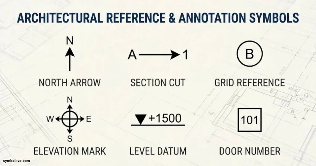
Not every mark on a floor plan represents a physical object. Some symbols tell you where to find more information elsewhere in the drawing set.
These are called architectural annotation symbols or drawing reference symbols. They connect the floor plan to elevations, sections, enlarged details, schedules, and other technical documents.
| Reference symbol | Meaning | Purpose |
| Section marker | Building section reference | Points to a cut-through view |
| Elevation marker | Interior or exterior elevation | Identifies a view from a particular direction |
| Detail callout | Enlarged detail reference | Directs you to a more detailed drawing |
| Grid bubble | Structural or planning grid reference | Identifies grid lines using letters or numbers |
| North arrow | Drawing orientation | Shows the direction of north |
| Level marker | Floor or elevation level | Identifies a vertical height or datum |
| Room tag | Room identification | Connects a room to its name or number |
| Door tag | Door identification | Links to the door schedule |
| Window tag | Window identification | Links to the window schedule |
| Revision cloud | Changed drawing area | Highlights an update or modification |
Section Symbols
A section symbol usually includes an arrow or pointer and a drawing reference. It identifies where the building is imagined to be cut so the viewer can see internal construction or vertical relationships.
For example, a section marker may point through a staircase. The corresponding section drawing can show stair height, floor levels, ceiling height, and headroom that are difficult to understand from the plan alone.
Elevation Symbols
An elevation marker identifies a view looking toward a wall or building face. Interior elevations are especially useful for kitchens, bathrooms, and built-in storage.
A kitchen elevation can show cabinet heights, worktop levels, wall units, and appliance positions. The floor plan shows where the kitchen is located, while the elevation shows what that wall looks like vertically.
Detail Callout Symbols
A detail callout directs you to an enlarged view of a particular component. It may identify a window junction, stair connection, wall assembly, or roof edge.
The callout often includes a detail number and a sheet number. For example, a marker might point to detail 3 on sheet A-501. The exact format depends on the drawing set.
Grid Bubbles and North Arrows
Grid bubbles identify structural or reference grid lines. They commonly use letters in one direction and numbers in another. These grids help the design and construction teams locate columns, walls, and other elements accurately.
A north arrow shows the orientation of the drawing. It is useful when assessing sunlight, building orientation, access, and the relationship between the floor plan and the actual site.
Room, Door, and Window Tags
Tags are compact labels that connect the plan to schedules or other documentation.
For example:
- 101 may identify a room number.
- D02 may identify a door type.
- W04 may identify a window type.
- A or B inside a room tag may identify a room finish or classification, depending on the project.
Never assume a tag’s meaning from its letters alone. Find the matching schedule or legend.
Floor Plan Lines, Patterns, and Drawing Conventions
Lines and patterns are just as important as individual symbols. Their thickness, style, and fill can communicate whether an element is cut, visible, hidden, above the viewing plane, or made from a particular material.
Line Weights in Architectural Drawings
Line weight refers to the thickness of a line on a drawing. Architects use different weights to create a visual hierarchy.
| Line weight | Common use |
| Very thick | Elements cut through by the plan view, such as walls |
| Medium | Visible edges, frames, and major objects |
| Thin | Dimensions, furniture, fixtures, and annotations |
| Very thin | Hatching, fine details, and construction guides |
A wall cut by the plan’s imaginary horizontal viewing plane often appears heavier than a cabinet or piece of furniture. This makes the building layout easier to read at a glance.
Line weight is not a universal measurement of construction thickness. A thick printed line does not necessarily mean a thick wall. Use dimensions and construction details to establish actual sizes.
Solid, Dashed, and Hidden Lines
Different line styles communicate different kinds of information.
- Solid lines: Usually show visible edges, walls, fixtures, and other elements in the plan view.
- Dashed lines: May show objects above the plan cut, hidden features, overhead cabinets, or items that are not visible at the current level.
- Center lines: Identify the center of a circular or symmetrical object, or establish an alignment reference.
- Break lines: Indicate that an element continues beyond the portion shown.
- Chain or dash-dot lines: May identify grid lines, center lines, or other reference information.
The meaning of a dashed line depends on its location and the drawing discipline. A dashed rectangle above a kitchen counter might represent an overhead cabinet, while a dashed line on a structural drawing could have a different meaning.
Hatch Patterns and Material Symbols
Hatching uses repeated lines, dots, or patterns to distinguish materials and construction assemblies. These marks are especially useful in sections and detail drawings.
| Pattern | Possible material or meaning |
| Diagonal parallel lines | Material cut in section or a generic hatch |
| Staggered rectangular pattern | Brick or masonry |
| Random dots or aggregate marks | Concrete |
| Wavy or zigzag pattern | Insulation |
| Grain-like lines | Wood |
| Earth or soil pattern | Ground or fill material |
| Solid dark fill | Cut material or a designated component |
Hatch patterns are not always identical across software or standards. Some offices use customized patterns, so check the drawing legend and material notes before identifying a material.
Dimensions and Scale
Dimensions explain the actual size and position of building elements. They may appear as extension lines, dimension lines, arrows, ticks, and numerical measurements.
Common dimension information includes:
- Overall building width and length
- Room dimensions
- Wall thicknesses
- Door and window openings
- Distances between structural grids
- Setbacks and clearances
- Distances from walls to fixtures
A drawing scale tells you how the drawing relates to real-world measurements. For example, a scale of 1:100 means one unit on the drawing represents 100 of the same units in reality. A scale of 1:50 shows more detail than a scale of 1:100 when printed at the intended size.
Do not rely on measuring a screenshot or resized PDF with a ruler. Digital viewers can zoom, and printed drawings can be scaled incorrectly. Use the written dimensions whenever they are available.
Common Floor Plan Abbreviations and Their Meanings
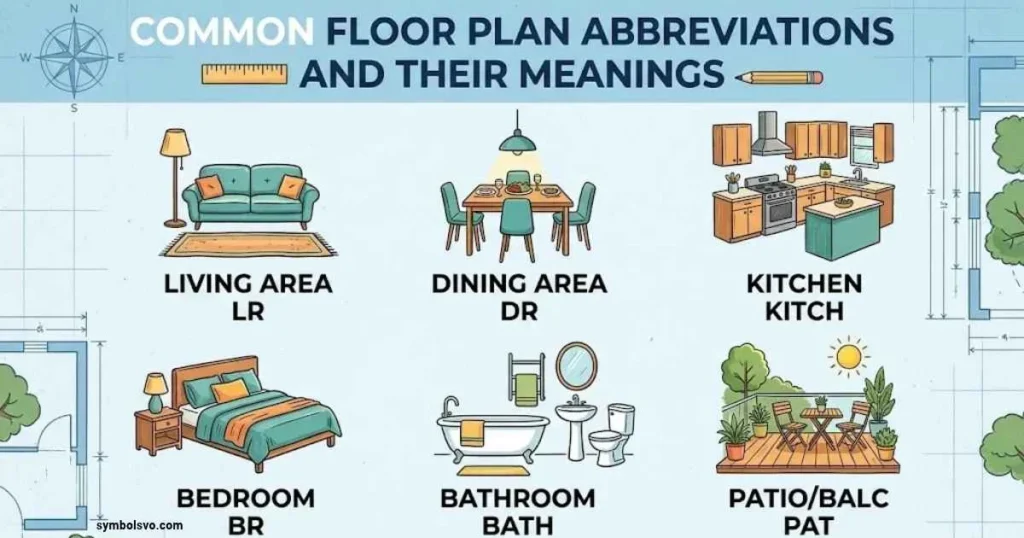
Architectural plans often use abbreviations to save space. These short labels can identify rooms, materials, fixtures, heights, and construction instructions.
The table below covers abbreviations you may encounter. Their meanings can differ by country, project, or drawing discipline.
| Abbreviation | Common meaning | Explanation |
| WC | Water closet | Toilet or toilet room |
| FFL | Finished floor level | Final floor surface elevation |
| AFF | Above finished floor | Height measured from the finished floor |
| CL | Centerline | Center reference of an element |
| NTS | Not to scale | Drawing is not shown at a measurable scale |
| TYP | Typical | Applies to similar repeated conditions |
| EQ | Equal | Indicates equal spacing or dimensions |
| UP | Up | Direction toward a higher level |
| DN | Down | Direction toward a lower level |
| OH | Overhead | May identify an overhead element |
| DW | Dishwasher | Kitchen appliance |
| REF | Refrigerator | Kitchen appliance |
| FD | Floor drain or fire damper | Meaning depends on drawing discipline |
| AHU | Air handling unit | HVAC equipment |
| EF | Exhaust fan | Mechanical ventilation equipment |
| GFCI | Ground-fault circuit interrupter | Electrical safety device |
| SD | Smoke detector or smoke damper | Depends on the drawing |
| EL | Elevation | Height or level reference in many plans |
| Ø | Diameter | Diameter of a circular element |
| TOS | Top of steel or top of slab | Meaning depends on context |
How to Read Floor Plan Abbreviations Correctly
Start by checking the title and discipline of the drawing. An abbreviation on an electrical plan may mean something different on a mechanical plan.
Then look for a general notes sheet, abbreviation list, or project legend. Many drawing sets include a dedicated page that defines the terms used throughout the project.
If an abbreviation is not explained, do not guess when the meaning could affect construction. Ask the architect, engineer, or person responsible for the drawing.
How to Read Floor Plan Symbols Step by Step
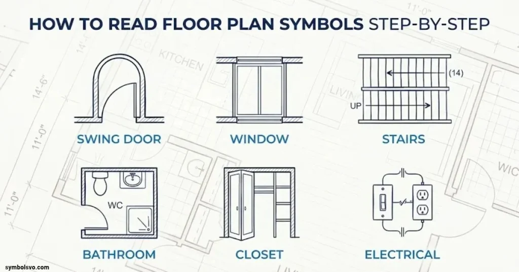
You don’t need to be an architect to understand a basic floor plan. A consistent reading process can help you interpret the layout and locate the details that matter.
Start With the Title Block and Drawing Number
Look at the title block, usually positioned along the bottom or side of the sheet. It identifies the project, drawing title, sheet number, scale, date, and design team.
A drawing number may also indicate its discipline. For example, architectural sheets often use an A prefix, while structural, mechanical, and electrical sheets may use different prefixes. These conventions vary by organization.
Check the revision information too. If you have several versions of a drawing, make sure you are reading the latest approved issue.
Find the Floor Plan Legend
The floor plan legend explains the symbols and abbreviations used on the sheet or across the drawing set.
Look for:
- Wall and partition types
- Door and window symbols
- Electrical and lighting marks
- Plumbing fixtures
- Section and elevation references
- Line types and material patterns
- Common abbreviations
A legend is especially important when a drawing uses custom symbols. It prevents you from treating a project-specific mark as a universal architectural symbol.
Identify the Walls, Doors, and Windows
Next, trace the main walls to understand the building’s overall shape. Look for exterior walls, interior partitions, columns, and openings.
Then identify doors and windows. Follow each door swing to see how rooms connect and where circulation space is needed. Check window positions to understand which rooms receive daylight and where exterior views may be possible.
Pay attention to narrow passages and door conflicts. A door that opens into a tight hallway or blocks a cabinet may create a practical problem even when the plan looks attractive.
Read Room Names and Dimensions
Find the room labels and written measurements. A label such as BEDROOM 02 identifies the intended use, while the dimensions show the room’s size.
Compare the dimensions with the furniture shown. Ask yourself:
- Can a bed fit with enough space to move around it?
- Does the dining area allow chairs to be pulled out?
- Is there enough clearance around kitchen appliances?
- Can bathroom fixtures be used comfortably?
- Does the hallway provide a practical route between rooms?
The furniture symbols can help you visualize the space, but written dimensions are more reliable than the apparent size of objects on a screen.
Check Stairs and Floor Levels
If the building has more than one level, identify the stairs and look for UP, DN, and level markers.
Compare the floor plan with the corresponding plan for the floor above or below. This helps you understand how the stairwell, landings, and rooms line up vertically.
For complex layouts, use section drawings to confirm floor heights and stair geometry.
Follow Reference Markers to Other Drawings
Finally, follow section, elevation, and detail callouts. These references provide information that a floor plan cannot show on its own.
For example, a floor plan may show a window’s location, but an elevation or window schedule can explain its height, frame, glazing, and appearance.
A good rule is to treat the floor plan as one part of a larger drawing set. It explains the horizontal arrangement, while other drawings provide vertical views, construction details, and technical specifications.
Are Floor Plan Symbols Universal?
No. Many standard floor plan symbols are widely recognized, but not every symbol looks exactly the same in every country, company, or project.
A hinged door is commonly shown with a panel line and swing arc. However, the style of that arc, the line weights, and the door identification tag may differ. Electrical and mechanical symbols can vary even more because different countries and industries use their own conventions.
Three factors explain most of these differences:
Regional standards: Countries may follow different technical drawing standards and conventions.
Discipline-specific practices: Architectural, structural, electrical, plumbing, and mechanical drawings use different symbol sets.
Project-specific legends: Design teams may create or modify symbols to suit a particular building or documentation system.
For that reason, learning common symbols is a useful starting point, but the project legend remains the final reference for interpreting a specific drawing.
Floor Plan Symbol Standards and Architectural Drawing Guidelines
Architects and engineers use standards and drawing guidelines to make construction documents consistent. These systems help teams organize information, communicate design intent, and exchange digital files.
However, a standard does not mean every drawing worldwide uses one identical symbol library.
United States National CAD Standard (NCS)
The United States National CAD Standard (NCS) provides guidance for organizing and presenting building design and construction information. It brings together the AIA CAD Layer Guidelines, the Construction Specifications Institute’s Uniform Drawing System, and BIM implementation and plotting guidance from the National Institute of Building Sciences.
NCS Version 7 was released in September 2025. Its contents include drawing organization, CAD layer guidance, terms and abbreviations, symbols, and BIM-related guidance.
The NCS is useful for teams that need consistent drawing organization and clearer information exchange. Its adoption is voluntary in the United States, although individual owners and organizations may require it for their projects.
Construction Specifications Institute+1
BS 8541-2:2011
In the United Kingdom, BS 8541-2:2011 provides recommendations for 2D symbols of building elements used in construction drawings and building information modeling.
Its scope focuses on architectural and land registry symbols as a base for architecture, modeling, and planning activities. It does not attempt to define every mechanical, electrical, and plumbing symbol. Those more specialized symbols are left to the relevant technical organizations.
This distinction matters. A standard that covers architectural building-element symbols should not be treated as a complete reference for every symbol on an electrical or HVAC drawing.
AIA CAD Layer Guidelines and Uniform Drawing System
The AIA CAD Layer Guidelines help design teams organize drawing information into consistent layers. Layers allow users to control the visibility and management of elements such as walls, doors, dimensions, electrical features, and annotations.
The Uniform Drawing System (UDS) provides guidance for organizing and presenting construction documents. It covers sheet organization, drawing conventions, schedules, symbols, notations, and abbreviations. These resources form part of the US National CAD Standard.
Project-Specific and Discipline-Specific Standards
Even when a project follows a recognized standard, the design team may add its own requirements. A large building project might include separate architectural, structural, plumbing, electrical, fire protection, and mechanical symbol legends.
Before using a symbol library, confirm:
- Which standard or office convention the project follows
- Whether the drawing set includes a project-specific legend
- Which discipline produced the drawing
- Whether symbols have been customized
- Whether the drawing is preliminary, issued for review, or approved for construction
This small check can prevent major misunderstandings.
CAD and BIM Symbols in Architectural Floor Plans
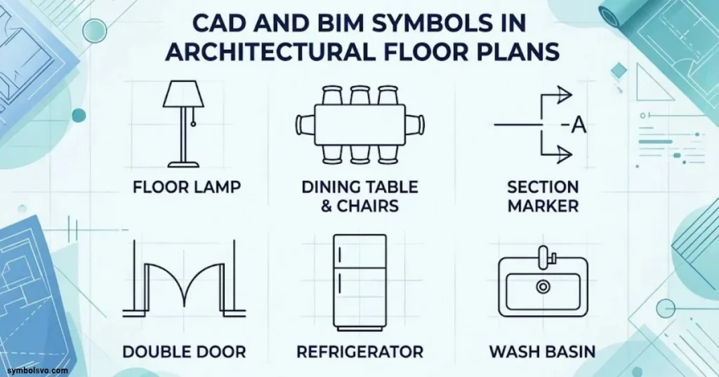
Modern architectural floor plans are often created using computer-aided design (CAD) and building information modeling (BIM) software. These tools make it easier to reuse symbols, revise drawings, and coordinate information across different disciplines.
CAD Blocks and Symbol Libraries
In CAD software, a symbol may be saved as a reusable CAD block. A door, window, sink, light fixture, or furniture item can be inserted into a drawing without recreating it each time.
Common CAD file formats include:
- DWG: A widely used drawing format associated with AutoCAD and compatible applications.
- DXF: A drawing exchange format used to transfer CAD information between applications.
- PDF: A common format for sharing and reviewing issued drawings.
CAD blocks can help teams maintain consistency. When a block is updated in a managed drawing, its instances can often be updated too.
However, a downloaded symbol library should not automatically be treated as suitable for a construction project. Check its scale, units, line weights, layer names, and graphic conventions before using it.
BIM Families and Intelligent Objects
BIM software uses objects that can contain more information than a simple 2D symbol. A door family, for example, may include its width, height, material, fire rating, manufacturer data, and 3D geometry.
A BIM model can generate a 2D floor plan view from the building model. The software displays the objects using the selected view settings and drawing conventions.
This creates a useful connection between the plan and the wider building model. A door shown in plan view can also appear in elevations, schedules, and 3D views.
2D Symbols Versus 3D BIM Objects
| Feature | 2D CAD symbol | 3D BIM object |
| Main purpose | Represent an element in a drawing | Represent an element in a building model |
| Geometry | Usually flat | Includes 3D geometry |
| Data | Often limited | Can include detailed properties |
| Reuse | Inserted as a block or symbol | Placed as a model component or family |
| Coordination | Depends on drawing management | Can support model-based coordination |
| Example | Door swing symbol | Door object with size and material data |
A 2D symbol is often enough for a simple diagram or early design plan. A BIM object becomes more useful when the team needs coordinated views, schedules, quantities, and detailed building information.
Common Mistakes When Identifying Floor Plan Symbols
Even familiar symbols can be misread when you overlook the drawing context. These mistakes are especially common among first-time home buyers, students, and people reviewing renovation plans.
Assuming Every Symbol Is Universal
A symbol that looks familiar may have a different meaning in another drawing set. Always check the legend, especially for electrical and mechanical symbols.
Confusing Dashed Lines With Wall Boundaries
A dashed line may represent an overhead cabinet, a hidden feature, or an element above the plan cut. It does not automatically indicate a wall.
Look at its position and compare it with nearby notes or other views.
Treating Every Thick Wall as Load-Bearing
Line weight helps distinguish elements graphically. It does not provide enough information to confirm structural function.
Check structural drawings and consult a qualified structural professional before removing or altering a wall.
Ignoring Door Swing Direction
A door can fit within an opening but still create a poor layout if it blocks circulation, furniture, or another door.
Check the swing arc and the available clearance around the opening.
Mixing Up Similar Abbreviations
Short labels can have different meanings across disciplines. SD, for example, may identify a smoke detector or a smoke damper.
Use the drawing title, discipline, and abbreviation legend to establish the intended meaning.
Measuring From a Resized Image
A screenshot may be stretched, compressed, or displayed at an unknown zoom level. Measuring it directly can produce inaccurate results.
Use written dimensions and the stated drawing scale. If you need to measure a digital drawing, confirm that the file and measurement settings are correct.
Ignoring Other Drawings in the Set
A floor plan cannot show every detail. It may identify a fixture’s location without explaining its installation, material, or exact specification.
Use the relevant elevation, section, detail, schedule, or engineering drawing to complete the picture.
Frequently Asked Questions About Floor Plan Symbols
What are the most common floor plan symbols?
The most common floor plan symbols represent walls, doors, windows, stairs, furniture, plumbing fixtures, electrical outlets, lights, and room labels. Architectural drawings also use dimensions, north arrows, section markers, elevation symbols, and detail callouts.
How do I read symbols on a house floor plan?
Start with the drawing title and legend. Identify the exterior walls, interior partitions, doors, and windows. Then read the room names and dimensions, check the stair direction, and follow any reference markers to other drawings. Use the written dimensions rather than estimating measurements from the image.
What does a curved line next to a door mean on a floor plan?
The curved line usually represents the door swing. It shows the direction in which a hinged door opens and the area its movement occupies. This helps you understand access and identify possible conflicts with furniture or nearby doors.
What does a dashed line mean on an architectural floor plan?
A dashed line can represent an overhead feature, hidden element, object above the plan cut, center reference, or another drawing convention. Its meaning depends on the location and drawing discipline. Check the legend and nearby annotations before interpreting it.
What does an arrow mean on a stair symbol?
A stair arrow generally indicates the direction of travel. It may be accompanied by UP or DN to show whether the stair rises toward a higher floor or descends toward a lower one. Always check the floor level and related plan.
What does WC mean on a floor plan?
WC commonly stands for water closet. It identifies a toilet or a room containing a toilet. In some plans, the abbreviation labels the fixture; in others, it labels the room.
What does FFL mean on a floor plan?
FFL usually means finished floor level. It identifies the elevation of the final floor surface after finishes are installed. It is often used with a height or level reference.
What does AFF mean on architectural drawings?
AFF commonly means above finished floor. It describes a height measured from the finished floor surface, such as the mounting height of an electrical outlet, switch, or fixture.
Are electrical floor plan symbols the same everywhere?
No. Electrical symbols can vary by country, standard, software, and design office. A project legend should define the symbols used for lights, switches, outlets, detectors, and other electrical equipment. The electrical drawing and specifications provide additional installation information.
Where can I find a floor plan symbol legend?
Look near the floor plan, in the general notes, or on a dedicated legend sheet within the drawing set. Some projects include separate architectural, electrical, plumbing, and mechanical legends. If a symbol is missing from the legend, ask the designer or engineer responsible for that drawing.
What is the difference between a floor plan and a blueprint?
A floor plan is a top-down drawing that shows the arrangement of spaces and building components on a particular level. A blueprint is a broader term commonly used for technical construction drawings, although modern construction documents are usually shared as digital CAD files or PDFs rather than traditional blueprints.
Can I identify a load-bearing wall from a floor plan?
Not reliably from a basic floor plan alone. Wall thickness, line weight, and location can provide clues, but they do not confirm structural function. Review the structural drawings and consult a qualified structural engineer before making changes.
What is the difference between CAD symbols and BIM symbols?
CAD symbols are generally 2D graphic elements used in technical drawings. BIM objects can contain 3D geometry and data such as dimensions, materials, and product information. BIM models can also generate 2D symbols and plan views from their objects.
Conclusion
Understanding floor plan symbols and meanings makes architectural drawings much easier to read. Walls define spaces, door arcs show opening direction, window marks identify openings, and stair arrows explain movement between floors. Other symbols communicate furniture placement, plumbing fixtures, electrical devices, HVAC components, dimensions, and drawing references.
Start with the legend, then work through the plan from the overall layout to the smaller details. Pay attention to line styles, abbreviations, dimensions, and reference markers. Most importantly, remember that symbols can vary between projects and disciplines.
Once you know the common conventions, you can read a floor plan with greater confidence, compare layouts more accurately, and ask better questions before buying, renovating, or building a property.

I’m Nathan Holloway, a passionate researcher and writer with a deep interest in symbols, signs, and their hidden meanings. I enjoy exploring how symbols have influenced different civilizations, religions, and modern communication. Through my work, I aim to make complex historical and cultural concepts easy to understand for readers of all backgrounds. Every article I write is carefully researched to provide reliable and engaging information.
Books:
- Beyond the Symbol
- The Secret Meanings of Everyday Signs
Author 2: Grace Whitmore
Description:
My name is Grace Whitmore, and I love discovering the stories behind the world’s most fascinating symbols. I spend my time researching ancient civilizations, mythology, spiritual traditions, and modern iconography to uncover the meanings people often overlook. I believe that every symbol has a history worth telling, and I enjoy sharing that knowledge in a simple and reader-friendly way.
Books:
- Echoes of Ancient Symbols
- The Symbolic World
 Daniel Brooks
 Mason Ellington