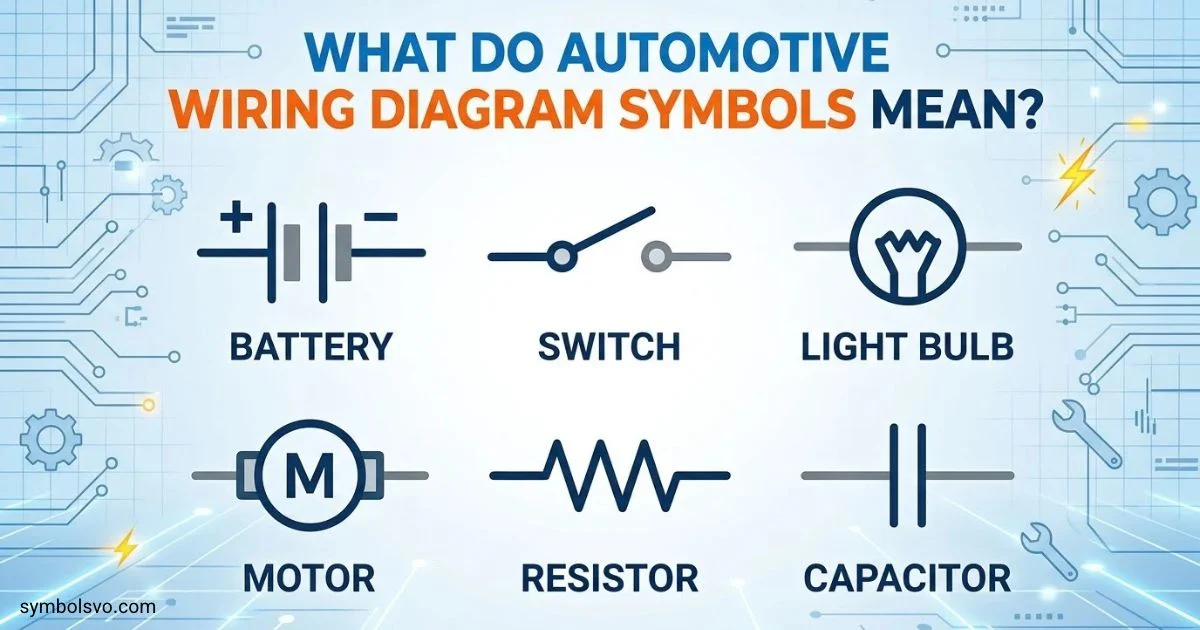
Electrical drawings use symbols to explain how a building’s electrical system should be arranged. From lights and outlets to circuit breakers, wiring connections, and communication devices, each symbol helps engineers, electricians, contractors, and designers understand the planned installation.
An electrical symbols chart makes these drawings easier to read. Instead of guessing what a circle, line, letter, or abbreviation represents, you can use a reference chart to identify the component and understand its purpose.
However, not every drawing follows exactly the same symbol conventions. Electrical floor plan symbols can differ from circuit schematic symbols, and project-specific legends may use custom abbreviations. For accurate interpretation, always check the drawing legend and applicable standards.
This guide covers electrical symbols and meanings, electrical plan symbols, lighting and outlet symbols, wiring diagrams, electrical components, safety devices, communication systems, and common electrical abbreviations. It also explains how to read an electrical blueprint legend and interpret symbols in practical construction drawings.
What Are Electrical Symbols?
Electrical symbols are graphical signs, letters, and abbreviations used to represent electrical components and systems on technical drawings. They help communicate the location, function, connection, and type of equipment without requiring lengthy written descriptions.
For example, an electrical floor plan may use a small fixture symbol to show where a ceiling light belongs. A circuit schematic may use a different graphical symbol to explain how that light connects to a switch and power source.
These symbols support several kinds of electrical drawing conventions, including:
- Electrical floor plans: Show the planned location of lights, switches, receptacles, and equipment within a building.
- Electrical wiring diagrams: Explain how conductors and electrical devices connect.
- Circuit schematics: Show the functional relationships between electrical and electronic components.
- Single-line diagrams: Simplify power distribution systems by representing circuits and equipment with a single line.
- Panel schedules: List circuit numbers, loads, and the equipment supplied by an electrical panel.
- Electrical installation drawings: Communicate the arrangement of equipment, cable routes, and other installation details.
The main purpose is clarity. A properly prepared drawing helps different professionals interpret the same design and coordinate their work.
Why Electrical Symbols Matter
Electrical symbols are essential during planning, construction, maintenance, and inspection.
They help professionals:
- Locate electrical fixtures before installation.
- Identify outlets and their intended uses.
- Understand switch and lighting control arrangements.
- Trace circuit relationships in technical diagrams.
- Identify distribution equipment and protective devices.
- Coordinate electrical work with architectural and mechanical plans.
- Reduce misunderstandings during construction.
- Document an installation for future repairs and renovations.
Symbols also save space. A single recognized graphic can communicate information that would otherwise require several words.
Electrical Symbols Chart With Names and Meanings
The following electrical symbols chart organizes common components by their function. Because floor-plan graphics differ from schematic graphics, the chart uses names and descriptions instead of pretending that one text character represents every official symbol.
Use it as a starting reference, then compare each entry with the legend on your actual drawing.
Common Electrical Symbols Chart
| Electrical symbol or label | Name | Meaning and common use |
| Light fixture mark | Light fixture | Indicates a planned lighting point |
| Recessed fixture mark | Recessed light | Shows a light installed within a ceiling |
| Pendant mark | Pendant light | Identifies a suspended lighting fixture |
| Wall fixture mark | Wall light | Indicates a fixture mounted on a wall |
| Ceiling fan mark | Ceiling fan | Shows the planned fan location |
| Duplex receptacle mark | Duplex outlet | Represents a receptacle with two outlet positions |
| GFCI label | GFCI receptacle | Identifies ground-fault circuit-interrupter protection |
| Switched receptacle label | Switched outlet | Indicates an outlet controlled by a switch |
| Floor outlet mark | Floor receptacle | Shows a receptacle installed in the floor |
| Single-pole switch label | Single-pole switch | Controls a lighting circuit from one location |
| Three-way switch label | Three-way switch | Supports control from two locations in typical US terminology |
| Four-way switch label | Four-way switch | Supports control from three or more locations when used with compatible switches |
| Dimmer label | Dimmer switch | Adjusts compatible lighting levels |
| Electrical panel label | Panelboard | Identifies a distribution panel |
| CB or breaker label | Circuit breaker | Represents an overcurrent protective device |
| Disconnect label | Disconnect switch | Identifies equipment used to isolate power |
| JB | Junction box | Marks an enclosure where conductors connect or branch |
| GND or ground symbol | Ground | Identifies a grounding connection or reference |
| Fuse symbol | Fuse | Represents a protective device designed to interrupt excessive current |
| Transformer symbol | Transformer | Represents equipment that transfers electrical energy between circuits |
| Motor symbol | Electric motor | Identifies a device that converts electrical energy into mechanical motion |
| Generator symbol | Generator | Represents equipment that produces electrical power |
| Battery symbol | Battery | Indicates a direct-current energy source |
| AC source symbol | Alternating-current source | Represents a source of alternating voltage |
| DC source symbol | Direct-current source | Represents a source of direct voltage |
| Resistor symbol | Resistor | Represents resistance in an electrical or electronic circuit |
| Capacitor symbol | Capacitor | Represents a component that stores electrical energy in an electric field |
| Inductor symbol | Inductor | Represents a component that stores energy in a magnetic field |
| Diode symbol | Diode | Represents a semiconductor device that primarily conducts in one direction |
| LED symbol | Light-emitting diode | Represents a semiconductor light source |
| Relay symbol | Relay | Represents an electrically controlled switching device |
| Contactor symbol | Contactor | Represents a switching device commonly used for power loads |
| Smoke detector mark | Smoke detector | Identifies a planned smoke-detection device |
| Heat detector mark | Heat detector | Identifies a heat-detection device |
| Exit sign mark | Exit sign | Shows the location of an illuminated exit indicator |
| Emergency light mark | Emergency lighting | Identifies lighting intended for emergency conditions |
| Data outlet mark | Data outlet | Indicates a communication connection point |
| Telephone outlet mark | Telephone outlet | Identifies a telephone connection point |
| TV outlet mark | Television outlet | Shows a television signal connection point |
| Wi-Fi AP label | Wireless access point | Identifies a network access point |
| Camera mark | Security camera | Indicates a planned surveillance camera |
| Thermostat label | Thermostat | Identifies a temperature-control device |
| Fan label | Ventilation fan | Indicates a fan or ventilation equipment connection |
Remember: The exact graphical symbol may look different from one drawing set to another. A label such as “GFCI” or “JB” is often clearer in a compact chart than an invented ASCII drawing.
Electrical Floor Plan Symbols
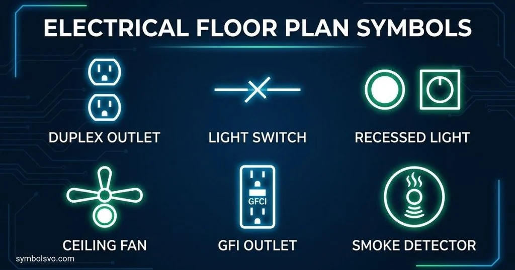
Electrical floor plan symbols show where electrical devices and equipment will be located within a building. They appear on architectural floor plans or dedicated electrical layouts and are used to coordinate fixture placement with walls, doors, furniture, ceilings, and other building systems.
An electrical layout design may include:
- Lighting fixtures and their control switches.
- Wall and floor receptacles.
- Electrical panels and distribution equipment.
- Dedicated connections for appliances.
- Smoke detectors and emergency lighting.
- Data, telephone, and television outlets.
- Equipment connections for heating and ventilation.
- Circuit references and wiring routes.
For example, a kitchen plan may show countertop receptacles, refrigerator power, lighting, and a dedicated connection for cooking equipment. A bedroom plan may include ceiling lighting, wall switches, general-purpose receptacles, and data outlets.
Main Types of Electrical Plan Symbols
| Category | What the symbols identify | Why they matter |
| Lighting | Ceiling lights, wall lights, pendants, and other fixtures | Communicate lighting locations |
| Power | Receptacles, appliance outlets, and equipment connections | Identify where electrical power is available |
| Switching | Switches and control devices | Explain how fixtures or loads are controlled |
| Distribution | Panels, breakers, transformers, and disconnects | Show major power equipment |
| Safety | Smoke detectors, emergency lights, and related devices | Coordinate safety-system placement |
| Communications | Data, telephone, television, and wireless devices | Support network and communication planning |
| Mechanical equipment | Fans, heaters, air-conditioning equipment, and controls | Coordinate electrical connections for mechanical systems |
How Floor Plan Symbols Differ From Schematic Symbols
A floor plan focuses on where equipment is located. A schematic focuses on how a circuit functions.
For example, a floor plan might show a ceiling light near the center of a room and a switch beside the entrance. The schematic may instead show the electrical relationship among the power source, switch contacts, and light.
Both drawings are useful, but they answer different questions. Never assume that a floor-plan symbol provides all the connection details needed to install or troubleshoot a circuit.
Lighting Symbols and Their Meanings
Lighting symbols identify the type and location of lighting fixtures on an electrical plan. They can also indicate fixture groups, control relationships, and special lighting requirements.
Common electrical lighting symbols include the following.
| Lighting symbol or label | Fixture type | Typical application |
| Ceiling fixture mark | Ceiling light | Bedrooms, living rooms, hallways |
| Recessed light mark | Recessed lighting | Kitchens, offices, corridors |
| Pendant fixture mark | Pendant light | Kitchen islands, dining areas |
| Wall fixture mark | Wall-mounted light | Bathrooms, hallways, exterior walls |
| Strip or linear fixture mark | Linear light | Offices, workshops, kitchens |
| Track lighting mark | Track light | Retail spaces, galleries, accent lighting |
| Emergency fixture mark | Emergency light | Designated emergency lighting locations |
| Exit sign mark | Exit indicator | Exit routes and building egress areas |
| Ceiling fan with light label | Fan-light combination | Rooms requiring both airflow and illumination |
| Exterior light mark | Outdoor light | Entrances, walkways, building perimeters |
The precise symbol depends on the drawing standard and the project legend. Some plans distinguish fixture types through different shapes, while others use letters or fixture codes.
Lighting Fixture Tags and Control References
Electrical drawings often assign a letter-number combination to each fixture type. For example, L1, L2, or F1 might identify different lighting types, but these labels are project-specific rather than universal.
A fixture schedule may explain each tag using information such as:
- Fixture type and manufacturer.
- Lamp or LED characteristics.
- Rated power and electrical requirements.
- Mounting method.
- Lighting output and color characteristics.
- Emergency or backup-power requirements, where applicable.
A separate control reference may indicate which switch operates a particular fixture or group. Lines between switches and fixtures can communicate control relationships, but their meaning depends on the drawing conventions.
Reading Lighting Symbols in Practice
Imagine a living-room plan with six recessed lights, one wall switch, and a pendant fixture over a dining table. The plan may distinguish the recessed fixtures from the pendant using separate graphics or fixture tags.
The legend identifies the fixture types, while the control notation explains which lights operate together. The fixture schedule then provides the technical details needed for selection and coordination.
This combination makes electrical fixture placement easier to understand without overcrowding the drawing with written descriptions.
Electrical Outlet Symbols and Their Meanings
Outlet symbols identify receptacles and other connection points for electrical equipment. Their shape, nearby letters, and notes may indicate the outlet type, mounting position, control method, or intended load.
An outlet shown on a plan does not automatically tell you its voltage, current rating, circuit assignment, or required protective features. Those details may appear in notes, schedules, panel information, or equipment specifications.
Common Electrical Outlet Symbols
| Outlet symbol or label | Name | Meaning |
| Duplex receptacle mark | Duplex outlet | A receptacle arrangement with two outlet positions |
| Single receptacle mark | Single receptacle | One receptacle outlet for a specified use |
| GFCI | Ground-fault-protected receptacle | Identifies a receptacle with ground-fault circuit-interrupter protection |
| AFCI notation | Arc-fault protection | Indicates an arc-fault protective requirement or associated device, depending on the drawing |
| S or switched note | Switched receptacle | Identifies an outlet controlled by a switch when defined by the legend |
| Floor box mark | Floor receptacle | Shows a receptacle in a floor-mounted box |
| Weather-resistant or outdoor note | Outdoor receptacle | Indicates an exterior or weather-exposed installation; exact protection requirements must be verified |
| USB label | USB receptacle | Identifies a receptacle that includes USB charging ports |
| Dedicated equipment label | Dedicated outlet | Indicates a connection intended for specified equipment |
| Appliance connection mark | Appliance outlet or connection | Identifies a connection point for an appliance or fixed equipment |
The words and letters shown above are common labels, not guaranteed graphic symbols. A designer may use another abbreviation or a project-specific symbol.
What Does a GFCI Outlet Symbol Mean?
A GFCI (ground-fault circuit interrupter) is a protective device designed to interrupt power when it detects a potentially dangerous imbalance between current flowing out and returning through the monitored conductors.
GFCI protection is especially relevant in locations where electrical equipment may be exposed to moisture or where the applicable electrical code requires it.
A GFCI label on a drawing helps identify the intended protection. It does not, by itself, establish every installation requirement. The designer and installer must check the applicable code, equipment instructions, and project specifications.
What Does a Switched Outlet Symbol Mean?
A switched receptacle is controlled by a switch. Depending on the design, the switch may control the entire receptacle or only one portion of a duplex receptacle.
This arrangement can allow a connected lamp or other suitable load to be controlled from a wall switch. However, a drawing’s symbol and legend must confirm the intended arrangement.
How to Read Outlet Labels
An outlet symbol may be accompanied by information such as:
- Mounting height or mounting location.
- Equipment identification.
- Circuit number.
- Voltage or current rating.
- Special protective requirements.
- Weather-resistant or other environmental classification.
- A reference to a dedicated circuit or panel schedule.
These details support accurate electrical plan interpretation. The symbol gives you the starting point; its annotations and the project documents supply the remaining information.
Electrical Switch Symbols and Their Meanings
Switch symbols identify devices that control lights, motors, and other electrical loads. The drawing may show a switch’s location, type, or relationship to other equipment.
Common switch types include single-pole switches, multi-location lighting controls, dimmers, and specialized control devices.
| Switch symbol or label | Switch type | Meaning |
| Single-pole switch label | Single-pole switch | Controls a circuit from one switching location |
| Double-pole switch label | Double-pole switch | Switches two poles together in an appropriate circuit |
| Three-way switch label | Three-way switch | US terminology for a switch used to control lighting from two locations |
| Four-way switch label | Four-way switch | US terminology for an intermediate switch used with compatible three-way switches |
| Dimmer label | Dimmer switch | Adjusts the brightness of compatible lighting |
| Occupancy sensor label | Occupancy sensor | Controls lighting or another load based on detected occupancy |
| Vacancy sensor label | Vacancy sensor | Uses occupancy detection but typically requires manual activation |
| Timer switch label | Timer switch | Controls a load according to a time setting |
| Pull-cord label | Pull-cord switch | Indicates a switch operated by a cord |
| Low-voltage control label | Low-voltage switch or control | Identifies a control device used in a low-voltage control system |
Single-Pole, Three-Way, and Four-Way Switches
In US electrical terminology, a single-pole switch commonly controls a lighting circuit from one location. A three-way arrangement allows control from two locations, while a four-way switch can be used between compatible three-way switches to add another control location.
Other countries may use different names for similar arrangements. This is one reason to check the terminology used by the drawing’s designer.
Understanding Switch-to-Light Relationships
A floor plan may show a switch near a doorway and a light fixture elsewhere in the room. A line or control reference may associate the switch with the fixture.
However, the drawing convention determines whether that line represents control, wiring, or another relationship. Do not treat every line on a floor plan as a physical cable route.
For accurate interpretation, check:
- The switch symbol and its type.
- Any letter or number beside the switch.
- The control line or reference, if present.
- The fixture schedule and legend.
- Any associated schematic or wiring diagram.
This helps prevent confusion between the location of a control device and the detailed electrical connections behind it.
Electrical Wiring and Schematic Symbols
Electrical wiring symbols and schematic symbols represent conductors, circuit connections, protective devices, and electrical components. Unlike a floor plan, a schematic generally emphasizes the functional relationships among components.
The official graphical representation depends on the applicable standard. The descriptions below explain common components without treating plain-text approximations as standardized drawings.
Common Electrical Wiring Symbols
| Symbol or notation | Component | Function |
| Straight line | Conductor or wire | Represents an electrical connection |
| Junction mark | Electrical junction | Indicates a connection between conductors according to the drawing convention |
| Crossing lines | Crossing conductors | May represent wires that cross without connecting, depending on the convention |
| Protective-earth symbol | Protective earth | Identifies a protective grounding connection |
| Ground reference symbol | Ground reference | Identifies a ground or reference connection within the circuit |
| Fuse symbol | Fuse | Protects a circuit by interrupting excessive current under specified conditions |
| Circuit-breaker symbol | Circuit breaker | Represents a resettable overcurrent protective device |
| Switch-contact symbol | Switch | Shows a device that opens or closes a circuit |
| Relay symbol | Relay | Represents electrically controlled switching |
| Contactor symbol | Contactor | Represents a switching device commonly used to control power loads |
| Transformer symbol | Transformer | Represents magnetic energy transfer between circuits |
| Terminal mark | Terminal | Identifies an electrical connection point |
| Connector symbol | Connector | Represents a separable electrical connection |
| Cable reference | Cable or cable assembly | Identifies a cable or cable group, often with a separate cable schedule |
Wires, Junctions, and Crossing Lines
A conductor is commonly represented by a line. But a line alone does not necessarily provide information about conductor size, insulation, material, or installation method.
A drawing may use a dot, junction mark, or another graphic to show that conductors connect. Crossing lines may follow a convention in which a crossing without a junction mark is not connected, but that rule should never be assumed without checking the drawing standard.
Cable and conductor information may appear in separate notes, wiring schedules, or circuit tables. These documents can identify cable types, conductor sizes, and other design requirements.
Grounding and Protective Earth Symbols
Ground-related symbols can represent different functions.
- Protective earth: A safety connection intended to help protect against electric shock under fault conditions.
- Ground reference: A reference node used to describe circuit voltages.
- Functional ground: A connection used for equipment performance or signal-related purposes.
- Bonding: The electrical connection of conductive parts to support the intended protective system.
These terms are related but not interchangeable in every context. A symbol’s meaning depends on the electrical system and the drawing standard.
Common Electronic Component Symbols
Electronic schematics use a different mix of component symbols. The following components are especially common.
| Component | Purpose | Typical context |
| Resistor | Limits or controls current and establishes voltage relationships | Electronic circuits |
| Capacitor | Stores energy in an electric field and affects circuit behavior | Filters, timing, power supplies |
| Inductor | Stores energy in a magnetic field | Filters, converters, transformers and related circuits |
| Diode | Conducts primarily in one direction | Rectification and signal circuits |
| LED | Produces light when appropriately energized | Indicators and lighting electronics |
| Transistor | Controls current or voltage and can provide switching or amplification | Control and electronic circuits |
| Transformer | Transfers energy between coupled windings | Power conversion and isolation applications |
| Battery | Provides a direct-current source | Portable devices and backup systems |
| AC source | Represents an alternating-current source | AC circuit analysis |
| DC source | Represents a direct-current source | DC circuit analysis |
| Motor | Converts electrical energy into mechanical motion | Pumps, fans, and machinery |
| Generator | Converts mechanical energy into electrical energy | Power-generation systems |
The symbol’s exact shape and orientation matter in formal circuit diagrams. When creating or reviewing engineering documentation, use the recognized symbol set for the applicable standard rather than copying a rough text representation.
Electrical Panel, Equipment, and Distribution Symbols
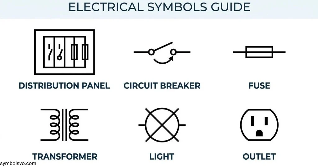
Electrical distribution symbols show how power is received, distributed, protected, and delivered to equipment. These symbols are important in residential, commercial, and industrial electrical system layout drawings.
A distribution plan may show the incoming supply, transformers, switchboards, panelboards, circuit breakers, disconnect switches, and major equipment connections.
Common Electrical Distribution Symbols
| Symbol or abbreviation | Equipment | Meaning |
| Panel or panelboard label | Panelboard | Identifies a group of branch-circuit protective devices and associated distribution equipment |
| MSB | Main switchboard | Identifies main power distribution equipment when defined by the project |
| MDB | Main distribution board | Common label for a main distribution board |
| DB | Distribution board | Identifies a distribution board; exact meaning depends on the project |
| CB | Circuit breaker | Identifies a circuit breaker |
| DS or disconnect label | Disconnect switch | Identifies equipment used to isolate a circuit or device |
| ATS | Automatic transfer switch | Transfers a load between designated power sources under its control scheme |
| XFMR or T | Transformer | Identifies a transformer; the exact label depends on the legend |
| CT | Current transformer | Provides a scaled current signal for measurement or protection |
| PT or VT | Potential or voltage transformer | Provides a voltage signal for measurement or protection |
| GEN | Generator | Identifies a generator |
| UPS | Uninterruptible power supply | Identifies equipment that supplies conditioned or backup power |
| SPD | Surge protective device | Identifies equipment intended to limit specified transient overvoltages |
| Meter symbol | Electrical meter | Identifies a measurement device |
| VFD | Variable-frequency drive | Controls an AC motor’s speed through adjustable frequency and voltage |
Abbreviations such as DB, MSB, and DS are not guaranteed to mean the same thing on every project. Always confirm them in the drawing legend.
Understanding Panel Schedules
An electrical panel schedule connects the drawing to the distribution system. It typically lists circuit identifiers, connected loads, breaker information, and other design details.
Depending on the project, a schedule may include:
- Circuit numbers.
- Load descriptions.
- Connected load or calculated load.
- Protective-device ratings.
- Phase information.
- Pole information.
- Spare or future circuits.
- References to equipment supplied by the panel.
For example, a schedule might identify one circuit for general lighting and another for a specified piece of equipment. The circuit number can then help a reader relate the plan to the panel schedule.
A panel schedule is not a substitute for the complete electrical design. Ratings, conductor sizes, protective-device coordination, and installation details must be determined and verified by qualified professionals.
Single-Line Diagram Symbols
A single-line diagram represents a power system using simplified connections and equipment symbols. One line may stand for a multi-conductor circuit when the drawing convention defines it that way.
Single-line diagrams are useful for showing:
- Incoming electrical supplies.
- Transformers and generators.
- Main and downstream distribution boards.
- Circuit breakers and disconnecting devices.
- Backup-power arrangements.
- Major loads and interconnections.
These diagrams help engineers understand the overall system without showing every physical conductor. Detailed wiring diagrams and schedules provide additional information where needed.
Electrical Safety, Fire Alarm, and Security Symbols
Safety and security symbols identify devices that protect occupants, support emergency response, or monitor access and activity. They may appear on dedicated safety-system drawings or coordinated electrical plans.
Common devices include smoke detectors, heat detectors, alarm notification appliances, emergency lights, exit signs, access-control equipment, and security cameras.
| Symbol or label | Device | Meaning |
| SD | Smoke detector | Detects smoke according to the device’s design |
| HD | Heat detector | Detects a specified heat condition |
| FA | Fire alarm system or reference | Identifies a fire alarm system or drawing designation |
| MCP or pull-station label | Manual fire alarm station | Identifies a device used to manually initiate an alarm |
| Horn or sounder mark | Audible notification device | Indicates a sound-producing alarm device |
| Strobe mark | Visual notification device | Indicates a visual alarm notification device |
| EL | Emergency light | Identifies emergency lighting when defined by the legend |
| EXIT | Exit sign | Identifies an exit indicator |
| CCTV | Video surveillance | Identifies a camera or video surveillance system reference |
| ACS | Access-control system | Identifies access-control equipment or system |
| Reader mark | Card reader | Shows a controlled-entry reader location |
| Door contact mark | Door position contact | Identifies a device that monitors door status |
| GFCI | Ground-fault circuit interrupter | Identifies ground-fault protection |
| AFCI | Arc-fault circuit interrupter | Identifies arc-fault protection where specified |
These abbreviations are common examples rather than a universal code. A project may use different labels or separate plans for fire alarm, security, and electrical power.
GFCI and AFCI: What Is the Difference?
GFCI and AFCI devices address different electrical hazards.
GFCI protection responds to certain current imbalances associated with ground faults. It is intended to reduce the risk of electric shock.
AFCI protection is designed to detect specified electrical arcing conditions that could contribute to fires.
Neither term should be treated as a generic label for every protective device. The required protection depends on the installation, equipment, location, and applicable electrical code.
Emergency Lighting and Exit Sign Symbols
Emergency lighting and exit signs help identify equipment associated with designated escape routes and emergency conditions. The drawings may show their locations, circuit references, and connections to an emergency power source.
The symbol alone does not confirm that the overall emergency system meets all requirements. Design and installation must account for the applicable building, fire, and electrical codes, along with the system’s specified performance.
HVAC, Heating, and Ventilation Symbols on Electrical Plans
Heating, ventilation, and air-conditioning equipment often needs electrical power and control connections. Electrical plans may therefore include HVAC equipment labels and references to mechanical drawings.
Common equipment includes fans, air-conditioning units, heat pumps, electric heaters, thermostats, pumps, and motorized equipment.
| Symbol or label | Equipment | Common purpose |
| EF | Exhaust fan | Removes air from a designated space |
| SF | Supply fan | Moves supply air through a ventilation system |
| AHU | Air-handling unit | Circulates and conditions air |
| FCU | Fan-coil unit | Uses a fan and heat-exchange coil to condition air |
| AC | Air conditioner or alternating current | Meaning depends on the drawing context |
| HP | Heat pump | Provides heating and, in suitable systems, cooling |
| WH | Water heater | Identifies water-heating equipment |
| HTR | Heater | Identifies heating equipment |
| T or thermostat label | Thermostat | Measures or responds to temperature for control purposes |
| VFD | Variable-frequency drive | Provides variable-speed control for compatible motors |
| P | Pump | Identifies a pump when defined by the legend |
| M | Motor | Identifies a motor or motor connection, depending on the drawing |
Notice that AC may mean air conditioner in an equipment schedule or alternating current in a circuit diagram. Context determines the meaning of an abbreviation.
Coordinating Electrical and Mechanical Drawings
An electrical plan may identify the power connection for an air-handling unit, while a mechanical drawing provides airflow, ductwork, and equipment information.
The two plans need to agree on equipment identifiers and locations. Otherwise, the installation team may struggle to match the electrical connection to the correct mechanical unit.
Useful coordination information includes:
- Equipment identification tags.
- Power-supply requirements.
- Control wiring references.
- Disconnecting-device locations.
- Equipment schedules.
- Related mechanical drawing numbers.
- Notes identifying equipment supplied by others.
This coordination is an important part of reliable electrical construction drawings.
Data, Telephone, and Communication Symbols
Modern buildings require more than power and lighting. Communication drawings may identify data outlets, telephone connections, wireless access points, television connections, speakers, security devices, and network equipment.
These symbols help coordinate the building’s communication infrastructure with walls, ceilings, furniture, and other services.
| Symbol or label | Name | Meaning |
| DATA | Data outlet | Identifies a network connection point |
| TEL | Telephone outlet | Identifies a telephone connection point |
| TV or CATV | Television connection | Identifies a television or cable-television outlet, as defined by the plan |
| AP | Wireless access point | Shows the planned location of a wireless network device |
| TR or rack label | Telecommunications rack | Identifies a rack or equipment location when defined by the legend |
| SPK | Speaker | Identifies a speaker or audio connection |
| ANT | Antenna | Identifies an antenna or antenna connection |
| CCTV | Surveillance camera system | Identifies a video surveillance point or system reference |
| Fiber label | Fiber-optic connection | Identifies a fiber connection or related infrastructure |
| Intercom label | Intercom | Identifies a communication device or connection |
Are CAT5e and Cat6 Electrical Symbols?
No. CAT5e and Cat6 are cable-category designations associated with twisted-pair communications cabling. They are not universal graphical symbols for data outlets.
A drawing may place a cable-category note beside an outlet symbol or include the category in a cable schedule. The outlet graphic indicates the connection point, while the cable designation specifies the intended cabling type.
Similarly, labels such as AP, DATA, and TEL may be used on communication plans, but their exact presentation depends on the project legend.
Why Communication Symbols Matter
Communication layouts help designers plan device placement and infrastructure before walls and ceilings are completed. They also support coordination among electrical contractors, network installers, security teams, and other trades.
For example, a meeting room may require data outlets, wireless access points, a display connection, and speakers. A coordinated plan helps the team identify those locations and match them with the correct schedules and specifications.
Electrical Symbols and Abbreviations Chart
Electrical drawings use both graphical symbols and written abbreviations. Symbols represent devices or connections, while abbreviations provide compact labels for equipment, measurements, systems, and technical details.
Common Electrical Units and Abbreviations
| Abbreviation | Full term | What it measures or identifies |
| AC | Alternating current | Current that periodically changes direction |
| DC | Direct current | Current that flows in one direction |
| V | Volt | Electrical potential difference |
| A | Ampere | Electric current |
| W | Watt | Active power |
| VA | Volt-ampere | Apparent power |
| Ω | Ohm | Electrical resistance |
| Hz | Hertz | Frequency |
| kV | Kilovolt | One thousand volts |
| mA | Milliampere | One-thousandth of an ampere |
| kA | Kiloampere | One thousand amperes |
| AWG | American Wire Gauge | A wire-size designation used in North America |
| kW | Kilowatt | One thousand watts |
| kWh | Kilowatt-hour | A unit of electrical energy |
| PF | Power factor | A measure of the relationship between active and apparent power under specified conditions |
| THD | Total harmonic distortion | A measure of harmonic distortion in a waveform |
Common Electrical Drawing Abbreviations
| Abbreviation | Meaning |
| CB | Circuit breaker |
| GFCI | Ground-fault circuit interrupter |
| AFCI | Arc-fault circuit interrupter |
| ATS | Automatic transfer switch |
| CT | Current transformer |
| PT / VT | Potential transformer / voltage transformer |
| JB | Junction box |
| GND | Ground |
| LED | Light-emitting diode |
| CATV | Cable television |
| UPS | Uninterruptible power supply |
| SPD | Surge protective device |
| VFD | Variable-frequency drive |
| DB | Distribution board, where defined that way |
| MDB | Main distribution board, where defined that way |
| MSB | Main switchboard, where defined that way |
| EF | Exhaust fan |
| AHU | Air-handling unit |
| AP | Wireless access point, when used in communication plans |
| FA | Fire alarm system or related designation, depending on context |
Some abbreviations have multiple meanings. For example, T may refer to a transformer, a thermostat, or another item depending on where it appears. AC can identify alternating current or air-conditioning equipment.
Never interpret an abbreviation in isolation when a drawing legend is available.
How to Read an Electrical Plan Legend
An electrical blueprint legend explains the symbols, labels, line types, and abbreviations used in a drawing set. It is often one of the most useful sections of an electrical plan because it defines the designer’s conventions.
A legend may include fixture graphics, outlet symbols, switch types, equipment abbreviations, line styles, and references to schedules.
Steps for Using an Electrical Legend
- Locate the legend. Check the electrical drawing sheets and the general notes. The legend may appear on a cover sheet or a dedicated electrical sheet.
- Identify the symbol. Find the matching graphic or abbreviation in the legend.
- Read the full description. Check whether the entry identifies a device, location, circuit, control function, or protective feature.
- Review nearby annotations. Letters, numbers, dimensions, and equipment tags may add essential details.
- Check related schedules. Lighting schedules, panel schedules, and equipment schedules often provide information not shown by the symbol itself.
- Follow drawing references. A symbol may refer to another sheet or a separate system diagram.
- Confirm revisions. Ensure that you are reading the current drawing revision rather than an outdated version.
Example: Interpreting a Bedroom Plan
Imagine a bedroom drawing that shows a ceiling fixture, two wall receptacles, and a switch beside the entrance.
You could interpret the drawing as follows:
- The ceiling fixture mark identifies a planned light location.
- The receptacle marks identify connection points.
- The switch mark identifies a control location.
- A nearby fixture tag may link the light to a lighting schedule.
- A circuit number may connect a receptacle or fixture to a panel schedule.
The legend confirms what the marks mean. The associated schedules and notes provide further details.
What If a Symbol Is Missing From the Legend?
Do not guess. Check the general notes, related sheets, drawing revision, and project specifications. If the symbol remains unclear, ask the responsible designer or qualified electrical professional for clarification.
A project-specific symbol may be valid within its drawing set even if it does not appear in a general-purpose chart.
Electrical Drawing Standards and Code Considerations
Electrical symbols are influenced by drawing standards, national practices, and project requirements. Two important references are NECA 100-2024 for electrical construction drawings in North America and IEC 60617 for graphical symbols used in electrotechnical diagrams.
These references serve related but distinct purposes.
- NECA 100-2024: Symbols for Electrical Construction Drawings describes graphical symbols used to represent electrical wiring and equipment on construction drawings.
- IEC 60617: Graphical Symbols for Diagrams provides an international database of graphical symbols for electrotechnical diagrams, including conductors, components, protective devices, instruments, and communication equipment.
- NFPA 70: National Electrical Code provides electrical installation requirements for jurisdictions that adopt it. It is a safety code, not simply a symbol dictionary.
Are Electrical Symbols Universal?
No. Many symbols are widely recognized, but not every electrical symbol is universal.
Differences can occur because of:
- National and regional standards.
- Floor-plan versus schematic conventions.
- Architectural versus industrial drawing practices.
- Company-specific drafting systems.
- Project-specific symbols and abbreviations.
- Different standards editions or drawing revisions.
A symbol used on a North American construction plan may differ from a symbol used in an IEC-based schematic. Even when two symbols look similar, their meaning should be verified.
Electrical Symbols Versus Electrical Codes
A drawing standard explains how information is represented. An electrical code establishes applicable installation and safety requirements. A design may also need to satisfy building codes, fire codes, equipment instructions, and local regulations.
For example, an outlet symbol identifies a receptacle location, but it does not independently establish the required mounting height, circuit rating, conductor size, or protective requirements.
The relevant requirements depend on the installation and the authority having jurisdiction. The 2026 edition of NFPA 70 is the current edition listed by NFPA, but a project must follow the edition and amendments adopted by its jurisdiction.
For projects outside the United States, consult the applicable local electrical regulations and adopted standards rather than assuming that US requirements apply.
How to Read Electrical Symbols on a Floor Plan
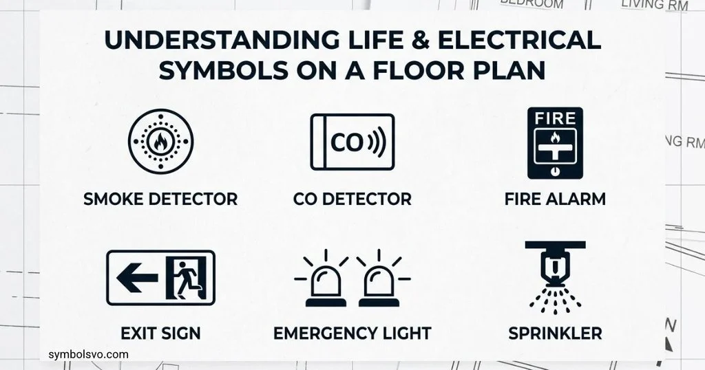
Understanding electrical plan symbols becomes easier when you read the drawing systematically. Start with the overall layout, identify each symbol, and then follow its references to schedules and other sheets.
Use this practical process:
Step 1: Review the drawing title and revision. Confirm that you have the correct floor, building area, and current version.
Step 2: Find the electrical legend. Learn the project’s specific symbols and abbreviations before interpreting the plan.
Step 3: Identify the major equipment. Locate distribution boards, panels, major equipment connections, and other important electrical elements.
Step 4: Review lighting and switching. Identify fixtures and switches, then check any control lines or references that connect them.
Step 5: Locate receptacles and outlets. Note the type, position, labels, and any references to dedicated equipment or special protection.
Step 6: Check circuit references. Follow circuit identifiers to the appropriate panel schedule or diagram.
Step 7: Compare related drawings. Review mechanical, architectural, fire alarm, and communication drawings when they affect the electrical layout.
Step 8: Check notes and schedules. Use these documents to confirm equipment specifications, installation details, and design requirements that symbols cannot communicate alone.
Step 9: Resolve unclear information. Ask the responsible designer or qualified professional rather than guessing.
This process supports accurate electrical plan interpretation and reduces the risk of confusing a device’s location with its wiring arrangement.
Common Mistakes When Reading Electrical Symbols
Even experienced readers can misinterpret electrical drawings when they overlook the legend, abbreviations, or related schedules.
| Common mistake | Why it causes confusion | Better approach |
| Assuming every symbol is universal | Different standards and projects may use different graphics | Check the project legend first |
| Confusing a floor plan with a schematic | The drawings communicate different kinds of information | Identify the drawing type before interpreting symbols |
| Treating every crossing line as a connection | Line-crossing conventions can vary | Check the junction marks and applicable drafting convention |
| Guessing the meaning of an abbreviation | The same letters can represent different items | Read the abbreviation in context |
| Ignoring fixture tags | A tag may link the symbol to a detailed schedule | Review the relevant fixture or equipment schedule |
| Assuming a receptacle symbol reveals its rating | The graphic may not specify electrical characteristics | Check circuit information, notes, and specifications |
| Confusing GFCI and AFCI protection | They address different electrical hazards | Confirm the exact protective function |
| Overlooking drawing revisions | An older sheet may conflict with the current design | Verify revision numbers and issue dates |
| Treating a single-line diagram as a physical wiring route | Simplified lines may represent complex circuits | Use the appropriate detailed wiring drawing |
| Relying on a general chart for installation decisions | General charts cannot capture every project requirement | Follow approved drawings, standards, and local codes |
A reliable rule is simple: the symbol, its legend entry, its annotations, and its related drawings must be read together.
Frequently Asked Questions About Electrical Symbols
What are the most common electrical symbols?
Common electrical symbols represent lights, switches, receptacles, conductors, circuit breakers, fuses, transformers, motors, grounding connections, and distribution panels. Communication and safety drawings may also include symbols for smoke detectors, emergency lights, data outlets, and security cameras.
The exact graphical representation depends on the drawing type and applicable standard.
What do electrical symbols mean on a floor plan?
Electrical symbols on a floor plan identify planned electrical devices and their locations. They may show lighting fixtures, receptacles, switches, panels, communication outlets, and equipment connections.
The legend and related schedules explain each symbol and provide additional information about the planned installation.
What is an electrical symbols chart used for?
An electrical symbols chart is a reference that helps readers identify components shown in electrical drawings. It is useful for students, designers, electricians, contractors, and anyone learning to interpret electrical plans.
A general chart provides a starting point, but the legend for the specific project should take priority.
What is the difference between electrical symbols and wiring symbols?
Electrical symbols are a broad category that includes symbols for devices, equipment, connections, and electrical systems. Wiring symbols specifically describe conductors, connections, terminals, and related wiring information.
The terminology can overlap, especially in schematic diagrams and construction drawings.
What does a circle mean on an electrical drawing?
A circle can represent different things depending on the drawing. It might identify a lighting fixture, a device location, a connection point, or another component.
Its shape alone is not enough to determine its meaning. Check the legend, nearby labels, and drawing type.
What does a switch symbol mean?
A switch symbol identifies a device used to control an electrical circuit or load. The accompanying label or graphic may distinguish a single-pole switch, multi-location control, dimmer, sensor, or another switching device.
The symbol does not necessarily show every internal connection.
What does GFCI mean on an electrical plan?
GFCI stands for ground-fault circuit interrupter. It identifies a protective device designed to interrupt power when it detects certain current imbalances associated with ground faults.
The drawing and applicable electrical requirements determine where and how this protection is provided.
Are electrical symbols the same in every country?
No. Electrical symbols vary by standards, region, drawing type, and project convention. North American construction drawings may use conventions that differ from IEC-based technical diagrams.
Always consult the project legend and the applicable standards.
Where can I find the legend on an electrical drawing?
The legend may appear on the cover sheet, a general electrical sheet, or a dedicated symbol-reference sheet. Some drawing sets also provide separate legends for lighting, power, fire alarm, and communication systems.
If you cannot find the legend, check the general notes and drawing index.
What do L, N, and G mean in electrical diagrams?
In many electrical diagrams:
- L means line or live conductor.
- N means neutral conductor.
- G may mean ground or grounding.
Exact terminology and conductor identification depend on the system and regional conventions. Never rely on a label alone to determine whether a conductor is safe to touch.
Which standards cover electrical symbols?
Two useful references are NECA 100-2024, which covers symbols for electrical construction drawings in North America, and IEC 60617, which provides graphical symbols for electrotechnical diagrams. The applicable standard depends on the drawing and project requirements.
Can I use an electrical symbols chart to install wiring myself?
A chart can help you understand a drawing, but it does not provide all the information required for a safe electrical installation. Correct installation requires appropriate training, approved design documents, suitable equipment, and compliance with local regulations.
For actual electrical work, consult a qualified electrician or other appropriately licensed professional.
Conclusion
An electrical symbols chart makes technical drawings easier to understand by connecting graphical marks with the devices, equipment, and systems they represent. Learning common electrical symbols and meanings helps you recognize lighting fixtures, outlets, switches, wiring connections, distribution equipment, safety devices, and communication components.
However, identifying a symbol is only the first step. You also need to understand the drawing type, check the electrical blueprint legend, read related schedules, and follow the applicable drawing standards and electrical codes.
Keep this chart as a quick reference while studying electrical floor plans, wiring diagrams, and construction drawings. For project-specific decisions, use the approved drawing set and consult a qualified electrical professional whenever a symbol or requirement is unclear.

I’m Daniel Brooks, a content creator and symbol enthusiast dedicated to researching the fascinating world of signs and symbols. I enjoy discovering the hidden meanings behind famous icons, emojis, historical emblems, and cultural symbols. Through my writing, I aim to provide trustworthy, well-researched, and reader-friendly information that helps people learn something new with every visit.
Books:
- The Complete Guide to World Symbols
- The Power of Universal Signs
 Nathan Holloway
 Mason Ellington